


- 15 -
3-4
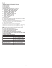
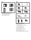
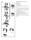
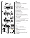
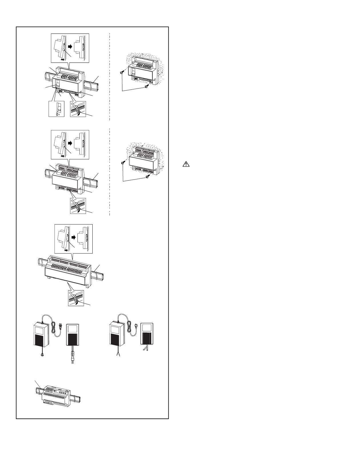
Bus Control Unit and Power Supply Adapter
[1] Din rail (W-DIN11)
[2] Screw hole
[3] POWER switch
[4] Power On LED (green)
[5] Lock release lever
[6] Wall mounting screws (x2)
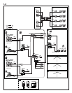
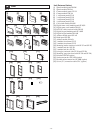
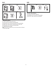
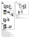
1. Mount GH-BC and GH-VBC to the Din rail. Click unit into
place.
∗ To remove GH-BC and GH-VBC, pull the lock release lever
down.
∗ If there is a problem with the system, check the power supply
wiring. Turn off the GH-BC and GH-VBC power switch and
then turn the switch back on after four seconds. This will reset
the entire system.
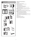
2. Mount GH-BC and GH-VBC directly to the wall surface.
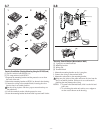
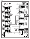
3. Mount GH-4Z to the Din rail.
∗ To remove GH-4Z, pull the lock release lever down.
4. Mount GH-4Z directly to the wall surface.
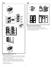
5. Mount GH-BCX and GH-VBX to the Din rail. To remove GH-
BCX and GH-VBX, pull the lock release lever down.
GH-BCX and GH-VBX cannot be mounted directly to the
wall surface.
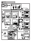
6. Power supply adapter PS-2410LC, PS-2410LD, PS-2410DIN
Red: +
Black: -
GH-BC
GH-VBC
GH-4Z
GH-BC
GH-VBC
GH-4Z
GH-BCX
GH-VBX
ON
OFF
[1]
[6]
[1]
[1]
[1]
[2]
[5]
[4]
[2]
[3]
[5]
[5]
[1]
[1]
[2]
[2]
[6]
12
3
5
6
4
+
–
+
–
+–
PS-2410LDPS-2410LC
PS-2410DIN
[1]