


Model CM-16 User Guide 25
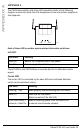
APPENDIX A
APPENDIX A
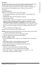
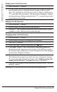
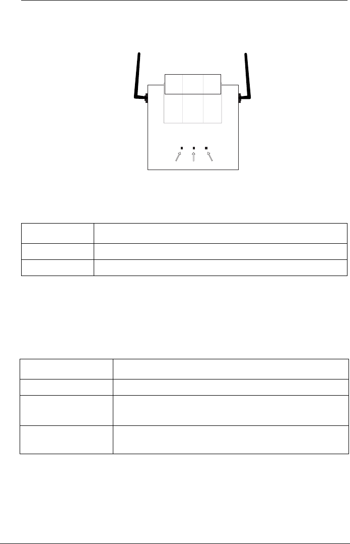
The CM-16 base station has three LED indicators. Refer to the following
diagram to correctly relate the LED designation to the information supplied in
this Appendix.
Each of these LED’s provides system status information as follows:
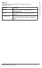
Left LED
The left LED on the CM-16 Base is currently tied to Vcc (Meridian switch
power).
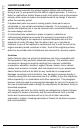
Center LED
The center LED is controlled by the base MCU and indicates Meridian
switch communications status.
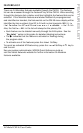
Led State Meaning
Solid Off Base is NOT supplied switch line power.
Solid On Base is supplied switch line power
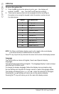
Led State Meaning
Flashing ~2Hz Base properly communicating with the switch.
Solid Off Base has no line power.
(Same as solid off for left LED)
Flash once every 2
seconds / Solid On
Base is receiving power from the switch but
is cannot communicate properly.
Left Center Right