


15
BP-2002
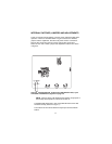
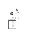
Type: One XLR-6M and XLR-6F pair (callout 7 in Figure 1)
Audiocom
®
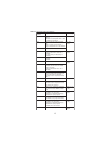
Mode (Internal switch SW1 and jumpers JP4, JP5, JP2 and
JP1 set to BAL position)
Pin 1 Common
Pin 2 Local power (+24 VDC)
Pin 3 Channel A intercom audio low and +24 VDC input
Pin 4 Channel A intercom audio high and +24 VDC input
Pin 5 Channel B intercom audio low and +24 VDC input
Pin 6 Channel B intercom audio high and +24 VDC input
Clear-Com Mode (Internal switch SW1 and jumpers JP4, JP5, JP2 and
JP1 set to UNBAL position)
Pin 1 Common
Pin 2 Local power (14 to 30 VDC)
Pin 3 Channel A +30 VDC input
Pin 4 Channel A intercom audio/call signal
Pin 5 Channel B +30 VDC input
Pin 6 Channel B intercom audio/call signal