


14
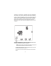
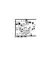
Note: In case of local power use, install a jumper on pins
2 & 3 of U6
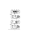
CONNECTOR PIN CONFIGURATIONS
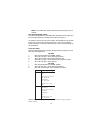
Headset Connector
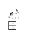
Type: XLR-4M (callout 6 in Figure 1)
Pin 1 Headset microphone low
Pin 2 Headset microphone high
Pin 3 Headphone high
Pin 4 Headphone low
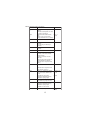
Intercom Channel Connectors
BP-1002
Type: One XLR-3M and XLR-3F pair (callout 8 in Figure 1)
Audiocom
®
Mode (Internal switch SW1 and jumpers JP4, JP5, JP2 and JP1
set to BAL position)
Pin 1 Common
Pin 2 Intercom audio low and +24 VDC input
Pin 3 Intercom audio high and +24 VDC input
Clear-Com Mode (Internal switch SW1 and jumpers JP4, JP5, JP2 and JP1
set to UNBAL position)
Pin 1 Common
Pin 2 +30 VDC input
Pin 3 Intercom audio/call signal