


6
Installation
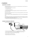
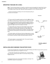
MOUNTING THE BASE ON A WALL
Note:
To mount the base directly on the wall, you need two screws (not supplied) with heads that fit into the
keyhole slots on the bottom of the base. Drill two holes 3
15
/
16
inches (100 mm) apart, one above the other.
Then thread a screw into each hole, letting the heads extend about
5
/
16
inch (7 mm) from the wall.
1
Remove the bracket by pressing on the arrows and gently pulling out
the wide end of the bracket.
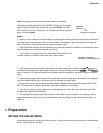
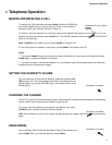
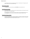
2
Plug one end of the supplied modular cord into the
LINE
jack. Route
the modular cord through the curved channel on the bottom of the base.
Then wrap any excess modular cord around the two crescent-shaped
tabs in the mounting bracket. Plug the supplied AC adapter’s barrel plug
into the
POWER
jack on the back of the base. Route the adapter cord
through the straight channel on the bottom of the base.
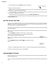
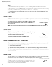
3
Insert the tabs on the narrow end of the bracket into the upper slots
on the bottom of the base. Insert the loose end of the modular cord
through the center of the bracket. Route the end of the adapter cord
through the opening on the wide end of the bracket. Then push the tabs
on the wide end of the bracket into the lower slots on the bottom of the
base.
4
Plug the modular cord’s other end into the wall plate jack (or a modu-
lar phone line jack), align the base’s keyhole slots with the wall plate studs
(or the screws in the wall), and slide the base downward to secure it.
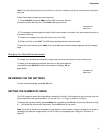
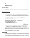
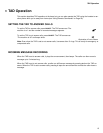
5
Plug the adapter into a standard AC outlet. Fully extend the base’s
antenna and raise it to a vertical position.
INSTALLING AND CHARGING THE BATTERY PACK
The SP-515 is packaged with a rechargeable nickel-cadmium battery pack. Before using your phone, you must
install the battery pack and then charge it for 10 hours.
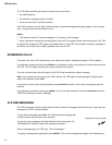
1
Press down and slide off the compartment cover. Plug the battery
pack connector into the phones socket. The connector fits only one way.
Replace the cover.
To charge the battery pack, simply place the handset on the base. The
CHARGING indicator on the base lights.
Illustration
LINE Jack
POWER Jack
Adapter
Upper Slots
Cord
Lower Slots
Illustration
Illustration - adapter to
outlet and antenna to
vertical
illustration of
base front with
handset on base