


NWZ-X1050/X1051/X1060/X1061
7
METHOD OF JUDGING RIGHT AND WRONG OF
PARTS RELATED TO SWITCH
In this set, only a part of parts that relate to the switch are supplied.
Exchange the entire mounted board when parts that do not corre-
spond to it are defective.
The right and wrong of the switch can be judged by the following
two methods.
1. Judgment From The Test Mode
Judge the right and wrong of the switch referring to “4-4-2. Key
check” (page 22).
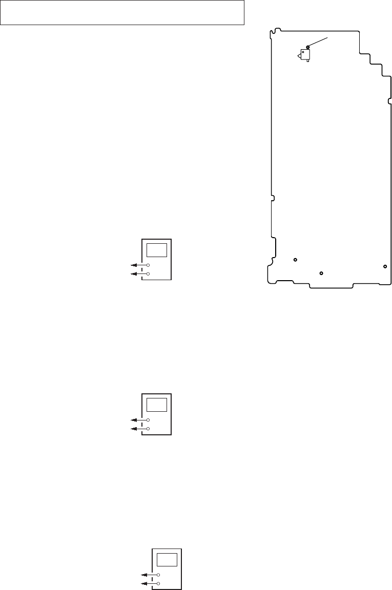
2. Judgment from the voltage measurement
Judge the right and wrong of the switch by the voltage measure-
ment with a test point.
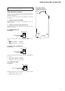
2-1. [
u]/[>]/[.] keys
Connection:
+
–
digital voltmeter
CL881 (KEY_AD0)
CL885 (GND)
When the voltage value is below, [u]/[>]/[.] keys are
normal.
• [u] key is pressed : 0 to 0.25 V
• [>] key is pressed : 0.4 to 0.6 V
• [.] key is pressed : 0.76 to 0.95 V
2-2. [VOL +]/[VOL –]/[HOME] keys
Connection:
+
–
digital voltmeter
CL882 (KEY_AD1)
CL885 (GND)
When the voltage value is below, [VOL +]/[VOL –]/[HOME] keys
are normal.
• [VOL –] key is pressed : 0 to 0.25 V
• [VOL +] key is pressed : 0.4 to 0.6 V
• [HOME] key is pressed : 0.76 to 0.95 V
2-3. HOLD switch (S881)
Connection:
+
–
digital voltmeter
S881 (HOLD SW pin 2)
CL885 (GND)
When the voltage value is below, HOLD switch (S881) is normal.
• HOLD switch is turned on : 2.85 V
• HOLD switch is turned off : 0 V
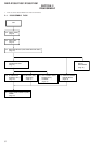
Connection location:
CL881
(KRY_AD0)
CL882
(KEY_AD1)
CL885
(GND)
S881
S881
(HOLD SW)
1
2
– MAIN Board (Side B) –
Note: Refer to page 27 for the schematic diagram. Refer to page
28 for the printed wiring boards.