


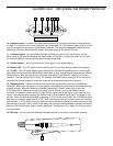
Guided Tour -
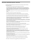
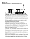
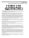
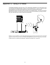
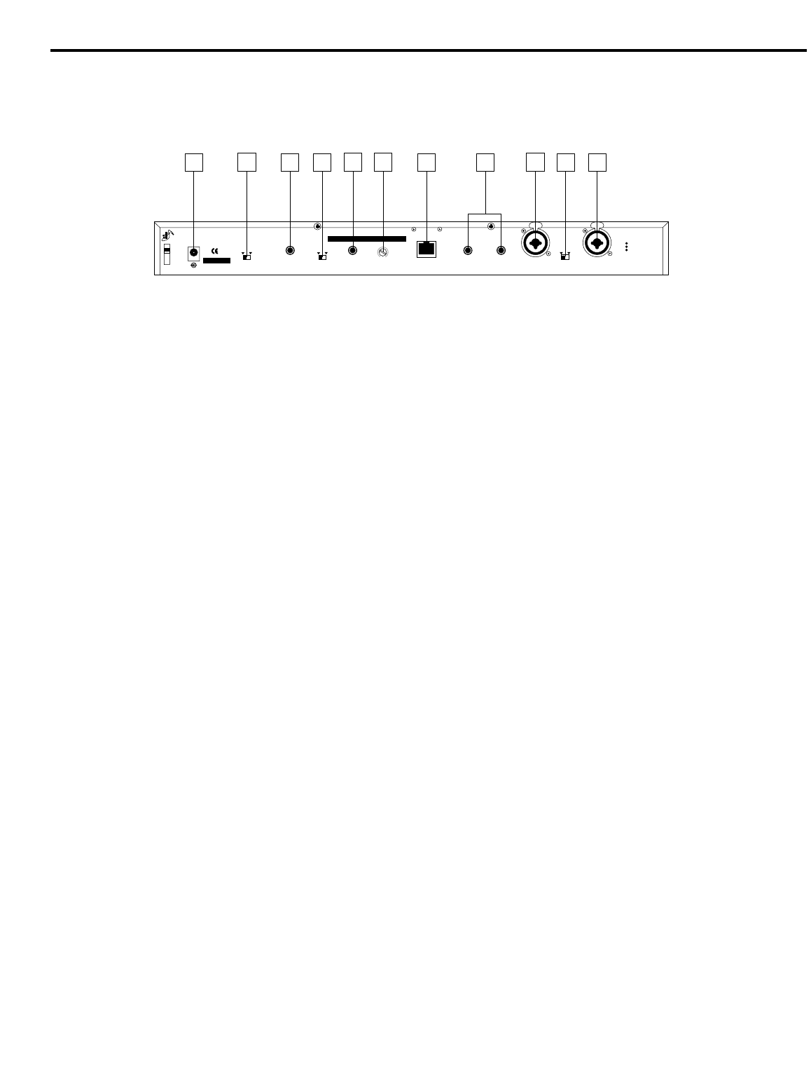
Wireless EarAmp® Transmitter Rear Panel
5
1: DC input - Connect the supplied power adapter here, using the strain relief as silkscreened on the
rear panel. WARNING: The substitution of any other kind of power adapter can cause severe damage to
the Wireless EarAmp® transmitter and will void your warranty.
2: Stereo/Mono switch - When set to “Stereo,” the incoming left and right audio signal(s) are kept
separate; when set to “Mono,” only signal connected to the left Main and.or Aux input (see #4 and #8
below) is used (the right signal is muted) and is transmitted to both channels of the receiver.
3: Aux Inputs - Use these two balanced 1/4" TRS (Tip/Ring/Sleeve) jacks when you wish to connect a
secondary signal to the Wireless EarAmp® transmitter. Wiring is Tip hot, Ring cold, and Sleeve ground.
We recommend the use of balanced three-conductor cabling wherever possible (unbalanced two-
conductor 1/4" plugs can also be inserted into these inputs, but you’ll get better signal quality and less
outside noise and hum if you use balanced lines). When connecting a monophonic signal, use the left
jack only and set the Stereo/Mono switch (see #2 above) to the “Mono” position.
4: Aux Input Attenuator switch - A 15 dB attenuator (pad) for the Aux inputs. In normal operation, this
switch should be set to the left “0 dB” position. If the incoming signal is too strong and is distorting, set
this to the right “-15 dB” position.
5: Aux Input Level control - Use a screwdriver to adjust this control until the desired level of Aux signal
(relative to the Main signal) is reached. If nothing is connected to the Aux Inputs (see #3 above), this
should be left at its fully counterclockwise position (completely off).
6: RJ45 Serial Port - Used to connect the Wireless EarAmp® transmitter to a computer for optional
remote control via software.
7: Daisy Chain Inputs/Outputs - These balanced 1/4" TRS (Tip/Ring/Sleeve) jacks are wired in parallel
with the Main inputs (see #8 below) and can be used to route the incoming Main signal to external
devices at unity gain. Alternatively, they can be used as inputs, bringing a third stereo or mono signal
into the Wireless EarAmp® transmitter (albeit without an attenuator switch or level control) if necessary.
Wiring is Tip hot, Ring cold, and Sleeve ground. See the “Setting Up and Using The Wireless EarAmp®”
section on page 8 of this manual for more information.
8: Main Inputs - Connect incoming signal to these electronically balanced Combination connectors,
using either XLR or 1/4" TRS (Tip/Ring/Sleeve) connectors, wired as follows: Pin 2 (or Tip) hot, Pin 3 (or
Ring) cold, and Pin 1 (or Sleeve) ground. We recommend the use of balanced three-conductor cabling
wherever possible (unbalanced two-conductor 1/4" cables can also be inserted into these inputs, but
you’ll get better signal quality and less outside noise and hum if you use balanced lines). When
connecting a monophonic signal, use the left jack only and set the Stereo/Mono switch (see #2 above) to
the “Mono” position.
9: Main Input Attenuator switch - A 15 dB attenuator (pad) for the Main inputs. In normal operation,
this switch should be set to the left “0 dB” position. If the incoming signal is too strong and is distorting,
set this to the right “-15 dB” position.
CAUTION
USE SAMSON
AC ADAPTOR
ONLY
DC INPUT
CABLE LOCK:
LOOP THRU
AND TIE
SERIAL NUMBER
SAMSON
RT80 UHF SYNTHESIZED
STEREO MONITOR TRANSMITTER
STEREO MONO
MADE IN USA
LEFT AUX INPUT
(MONO)
0dB -15dB
AUX INPUT
ATTENUATOR
RIGHT AUX INPUT
0
AUX INPUT LEVEL
AUXILIARY
RJ45 SERIAL PORT
INTERFACE
PARALLEL LEFT
IN/OUT
PARALLEL RIGHT
IN/OUT
DAISY CHAIN
1
2
3
PUSH
INPUT RIGHT
1
2
3
PUSH
INPUT LEFT (MONO)
MAIN INPUTS
0dB -15dB
ATTENUATOR
XLR
1 GND
2 HOT
3 COLD
A
+
-
-2
2
4-4
6
-6
8
-8
-10
10
1
2
3
4
3
5
6
7
8
9
8