


8
INSTALLATION
MOUNTING THE PHONE
You can place the TAD-794’s base on a
desk or table, mount it on a standard
wall plate, or mount it directl
y
on a wall.
Choose a location that is:
• near an AC outlet
• near a modular telephone line jack
• out of the wa
y
of normal activities
•awa
y
from electrical machiner
y
,
electrical appliances, metal walls or
filin
g
cabinets, wireless intercoms,
alarms, and room monitors
•awa
y
from other cordless phones
The base’s location affects the phone’s
ran
g
e. If
y
ou have a choice of several lo-
cations, tr
y
each to see which provides
the best performance.
Caution:
The supplied RadioShack
adapter was desi
g
ned specificall
y
for
y
our TAD-794. Use onl
y
the supplied
adapter.
Notes:
• Your telephone connects directl
y
to
a modular telephone line jack. If
y
our phone line jack is not a modu-
lar jack,
y
ou can update the wirin
g
y
ourself, usin
g
jacks and adapters
available at
y
our local RadioShack
store. Or,
y
ou can let the phone
compan
y
update the wirin
g
for
y
ou.
• The USOC number of the jack to be
installed is RJ11C (RJ11W for a wall
plate).
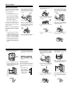
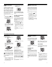
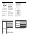
On a Desk Top
1. Insert the bracket’s tabs into the
base’s upper tab slots as shown,
then press down on the bracket’s
clips and insert them into the upper
clip slots.
2. Route the supplied lon
g
modular
cord throu
g
h the strain relief slot on
the side of the bracket, then plu
g
the
cord into the
TEL LINE
jack on the
back of the base.
3. Plu
g
the modular cord’s other end
into a modular telephone line jack.
Clips
Upper
Upper Tab Slots
Clip Slots
Strain
Relief
Slot
9
4. Insert the supplied AC adapter’s
barrel plu
g
into the
DC IN 9V
jack on
the back of the base.
5. Route the adapter’s cord throu
g
h
the strain relief slot on the bottom of
the bracket.
6. Plu
g
the adapter into a standard AC
outlet.
7. Lift the base’s antenna to a vertical
position.
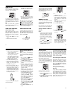
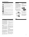
On a Wall Plate
1. Insert the bracket’s tabs into the
base’s lower tab slots as shown,
then press down on the bracket’s
clips and insert them into the lower
clip slots.
2. Plu
g
one end of the supplied short
modular cord into the
TEL LINE
jack
on the back of the base.
3. Insert the supplied AC adapter’s
barrel plu
g
into the
DC IN 9V
jack.
Strain
Relief
Slot
Tabs
Lower
Lower Clip Slots
Tab Slots
10
4. Route the adapter cord throu
g
h the
narrow
g
roove on the bracket.
5. Plu
g
the modular cord’s other end
into the wall plate jack, then ali
g
n
the bracket’s ke
y
hole slots with the
wall plate studs and slide the base
downward to secure it.
6. Plu
g
the adapter into a standard AC
outlet.
7. Press and lift out the handset hold-
er, flip it over as shown, then snap it
back into place so it holds the hand-
set.
8. Lift the base’s antenna to a vertical
position.
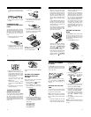
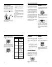
Directly on the Wall
For this mountin
g
method,
y
ou need two
screws (not supplied) with heads that fit
into the ke
y
hole slots on the bottom of
the base.
1. Drill two holes 3
15
/
16
inches (100 mm)
apart. Then thread a
screw into each hole,
lettin
g
the heads ex-
tend about
5
/
16
inch (8
mm) from the wall.
Narrow
Groove
5
/
16
"
3
15
/
16
"
11
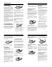
2. Insert the bracket’s tabs into the
base’s lower tab slots as shown,
then press down on the bracket’s
clips and insert them into the lower
clip slots.
3. Plu
g
one end of the supplied lon
g
modular cord into the
TEL LINE
jack
on the back of the base.
4. Insert the supplied AC adapter’s
barrel plu
g
into the
DC IN 9V
jack.
5. Route the modular and adapter’s
cords throu
g
h the
g
rooves on the
bracket as shown.
6. Ali
g
n the bracket’s ke
y
hole slots
with the mountin
g
screws and slide
the base downward to secure it.
7. Plu
g
the modular cord’s other end
into a modular telephone line jack.
8. Plu
g
the adapter into a standard AC
outlet.
Tabs
Lower
Lower Clip Slots
Tab Slots
Grooves