


SoundStation VTX 1000 Operation Manual
40
Administrator’s Guide
SoundStation VTX 1000 Operation Manual
41
Administrator’s Guide
Diagnostics
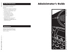
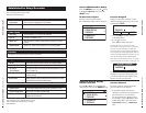
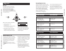
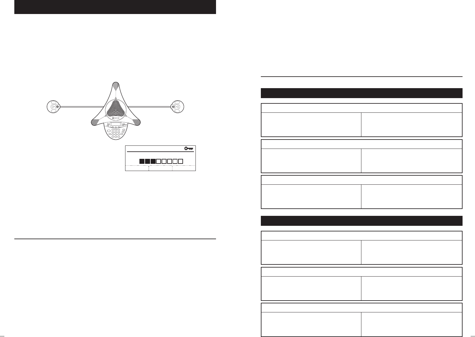
To test the SoundStation VTX 1000’s
microphones from within the Mic Test
portion of the Diagnostics section,
highlight the microphone you wish
to test, and then press the SELECT button.
The microphones are numbered according
to the diagram below:
Mic Test
MIC 1
MIC 3MIC 2
MIC 4 MIC 5
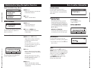
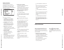
When you have selected a microphone:
That microphone’s LED
will light up red.
That microphone will begin sampling
at a 1 Hz rate, 50% duty cycle.
The display will show a meter that
modulates according to the relative
sample received by that microphone.
If a microphone’s meter indicates
that it is receiving an atypically low
or high sample, despite appropriately
controlled input, contact Polycom
Technical Support.
MIC TEST
mic 3 level meter
cancel
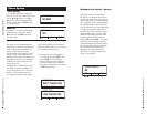
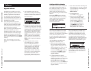
From the Console Speaker Test portion
of the Diagnostics section, you can select
an acoustic test signal to drive through
the SoundStation VTX 1000’s speaker
for speaker testing and to sample the
room acoustics.
Highlight the desired signal, and press
the SELECT button soft key to activate the
signal.
Sine Sweep is a test signal consisting of
a 100 Hz to 14,000 Hz sine wave whose
frequency is swept according to a linear
progression of frequency as a function
of time, or (t)=A*sin(kt).
One kHz Tone is a constant tone
generated at exactly 1000 Hz.
White Noise is a signal whose energy
is distributed uniformly among all
frequencies within a band of interest,
which for the SoundStation VTX 1000
is 100 Hz to 14,000 Hz.
Console Speaker Test
Polycom Wireless Mic
100 Hz < BW < 14 kHz 100 Hz < BW < 14 kHz
Zout < 200 ohms, typical Zin = 24k ohms, nom
Max Vout 0.25 Vpp to 1.0 Vpp
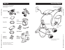
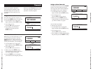
The External Speaker Test portion of the
Diagnostics section works just as described
above but drives the signal through the
audio output device you have connected,
such as a speaker, subwoofer, or PA
system. (See the Connection Diagram,
pg. 31, for setup of audio output devices.
See also “Aux Output,” pg. 19,
for information on configuration.)
Note: The External Speaker Test signals
can be used for the VTX Subwoofer
(see “Using the VTX Subwoofer,” pg. 22,
and also see “Aux Output,” pg. 19, for
information on configuration), but output
signal levels with the Subwoofer will not
exceed 300 Hz.
External Speaker Test
External Device Output Interface Module Input
Ext Mic
100 Hz < BW < 14 kHz 100 Hz < BW < 14 kHz
Audio out = 600 ohms, typical Zin = 24k ohms, nom
Level = 0.5 Vpp, nom
Ext Mixer
100 Hz < BW < 14 kHz 100 Hz < BW < 14 kHz
Audio out = 600 ohms, typical Zin = 24k ohms, nom
Level = 0.5 Vpp, nom
Subwoofer
80 Hz < BW < 300 Hz 80 Hz < BW < 300 Hz
Input impedance = 7k ohms, nom Output Impedance < 100 ohms
Sensitivity = 97 dBspl/Volt Output Level = 0.7 Vrms, max
External Device Input Interface Module Output
External Speaker(s)
80 Hz < BW < 14 kHz 80 Hz < BW < 14 kHz
Audio In = 10k ohms, typical Output Impedance < 100 ohms
Sensitivity = 100 dBspl/Volt, nom Output Level = 0.7 Vrms, max
Record Out
80 Hz < BW < 15 kHz 80 Hz < BW < 14 kHz
Audio in = 10k ohms, nom Output Impedance < 100 ohms
Level = 0.7 Vrms, max Output Level = 0.7 Vrms, max
Aux In and Aux Out Specication Table