


BUILDING YOUR SYSTEM WITH MULTIPLE VOR-
Vortex
®
Applications and Presets Guide 4 Technical Support: (800) 932-2774
be mixed with the other inputs to create Outputs 1-8, A-D, Ref 1, Ref 2, and W, X, Y,
and Z bus outputs.
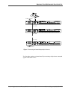
EF Bus Reference.
In a system with multiple devices, if all devices need the
same echo canceller reference, one device should be designated to put its echo cancel-
ler reference (either Ref 1 or Ref 2) on the EF bus to be used as the EF Bus Reference.
All other Vortexes
may use the EF bus reference as the reference for their echo can-
cellers, or they can use their own internal references. The references may include a
mix of any input, with crosspoint gains, including W, X, Y, and Z busses.
NOM Bus.
All busses on the EF Bus contain NOM information. See “NOM
Active” on page 29 of the Vortex Reference Manual for more information on how
NOM attenuation is applied.
4. C
ONFIGURE
Y
OUR
E
CHO
C
ANCELLER
R
EFERENCE
Review what inputs need to be included in your echo canceller reference — See
“Build Your Echo Canceller Reference (if not using Preset 0)” on page 13. of the Vor-
tex Reference Manual. Remember that each microphone needs an echo canceller ref-
erence. If all microphones are in the same room and use the same reference,
configure the echo canceller reference on one Vortex and assign it to the EF Bus as
the EF Bus Reference. Only one Vortex out of multiple units linked together can put
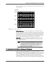
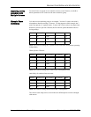
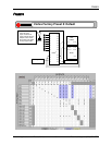
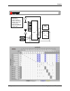
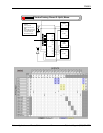
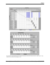
Figure 1. W, X, Y, and Z submatrices.
Submatrix
Bus W
W
B
0W
B
1W
B
2W
B
3W
B
4W
B
5W
B
6W
B
7
Bus X X
B
0X
B
1X
B
2X
B
3X
B
4X
B
5X
B
6X
B
7
Bus Y Y
B
0Y
B
1Y
B
2Y
B
3Y
B
4Y
B
5Y
B
6Y
B
7
Bus Z Z
B
0Z
B
1Z
B
2Z
B
3Z
B
4Z
B
5Z
B
6Z
B
7
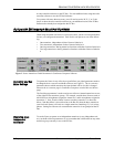
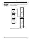
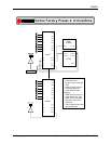
Note.
The EF Bus must be connected so that the EF B
US
O
UT
of one
Vortex device is connected to the EF B
US
I
N
of another Vortex.
Connecting EF B
US
I
N
to another EF B
US
I
N
(or EF B
US
O
UT
to
EF B
US
O
UT
) will not work. See“Connector Pinouts” on
page 43 for pinout of Cat 5 cable.