


INTRODUCTION
Vortex
®
Applications and Presets Guide 2 Technical Support: (800) 932-2774
I
NTRODUCTION
This manual describes useful application information and the factory presets of the
Vo r t e x
®
. The following is an overview of each section:
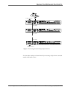
• Building Your System with Multiple Vortexes® outlines things you need to con-
sider as you build a system with mulitple Vortex units.
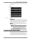
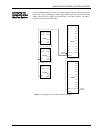
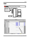
•Presets shows Factory Presets 0-6 in block diagram form and matrix settings.
These are meant to be used as examples. Vortex Factory Presets include the fol-
lowing:
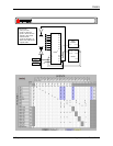
• Factory Preset 0: D
EFAULT
. Inputs 1-8 direct out; Inputs A-D mix minus to
Outputs A-D for room audio, codec, Phone Add, and/or program audio.
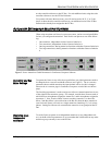
• Factory Preset 1: D
EFAULT
, S
TEREO
. Default configuration with stereo.
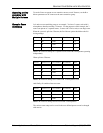
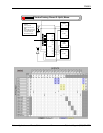
• Factory Preset 2: S
PLIT
. Vortex split between 2 rooms. Inputs 1-4, Output 1
go to Room 1; Inputs 5-8, Output 5 to Room 2. Input/Output A-B and Input/
Output C-D for codec and Phone Add in each room.
• Factory Preset 3: R
ESERVED
.
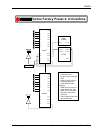
• Factory Preset 4: 8 M
ICS
/Z
ONE
. For applications with 8 microphones per
loudspeaker zone.
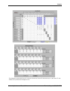
• Factory Preset 5: 8/Z
ONE
, S
TEREO
. 8 mics/zone with stereo.
• Factory Preset 6: 4 M
ICS
/Z
ONE
. For applications with 4 microphones per
loudspeaker zone.
• Factory Preset 7-12: R
ESERVED
for future use.
• Factory Preset 13: P
ASSTHROUGH
M
IC
. Passthrough mode (Inputs 1-8, A-D
are direct out) with Inputs 1-8 set to Mic level. Everything else is disabled.
• Factory Preset 14: P
ASSTHROUGH
L
INE
. Passthrough mode (Inputs 1-8, A-D
are direct out) with Inputs 1-8 set to Line level. Everything else is disabled.
• Factory Preset 15 B
LANK
S
LATE
. All crosspoints muted. Everything dis-
abled.