


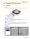
2.5 Installation of the Other Cards
Installation Manual 61
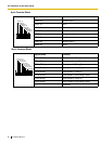
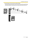
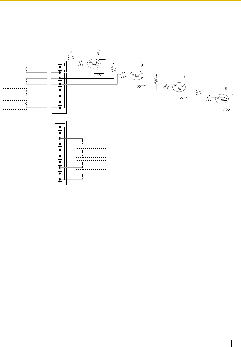
Connection Diagram for External Sensors and External Relays
Power to the external sensor is provided from the DPH4 card and must be grounded through the DPH4 card
as indicated in the diagram below. A pair of "sensor" and "common" lines must be connected to the DPH4
card for each external sensor. The PBX detects input from the sensor when the signal is under 100 Ω.
5 V
Sensor 4
Sensor 3
Sensor 2
Sensor 1
8
7
6
5
4
3
2
1
Relay 4
Relay 3
Relay 2
Relay 1
10
9
8
7
6
5
4
3
2
1
5 V
10K Ω
2.2K
47K
33 Ω
33 Ω
5 V
5 V
10K Ω
2.2K
47K
33 Ω
33 Ω
5 V
5 V
10K Ω
2.2K
47K
33 Ω
33 Ω
5 V
5 V
10K Ω
2.2K
47K
33 Ω
33 Ω
sensor
common
sensor
common
sensor
common
sensor
common