


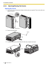
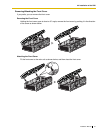

2.2 Installation of the PBX
34 Installation Manual
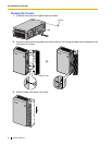
2.2.5 Frame Ground Connection
IMPORTANT
Connect the frame of the PBX to ground.
• Be sure to comply with applicable local regulations (e.g., law, guidelines).
• Proper grounding (connection to ground) is very important to protect the PBX from the bad effects of
external noise or to reduce the risk to the user of electrocution in the case of a lightning strike.
• The ground wire of the AC cable has an effect against external noise and lightning strikes, but it may
not be enough to protect the PBX. A permanent connection between ground and the ground terminal
of the PBX must be made.
In most of the continental United States, the ground provided by the "Third wire ground" at the commercial
power outlet will be satisfactory. However, in a small percentage of cases this ground may be installed
incorrectly. Therefore, the following test procedure should be performed.
Test Procedure
1. Obtain a suitable voltmeter and set it for a possible reading of up to 250 V AC.
2. Connect the meter probes between the 2 main AC voltage points on the wall outlet. The reading
obtained should be 108 V AC to 132 V AC.
3. Move one of the meter probes to the 3rd prong terminal (GND).
Either the same reading or a reading of 0 volt should be obtained.
4. If a reading of 0 volt at one terminal and a reading of 108 V AC to 132 V AC at the other terminal
is not obtained, the outlet is not properly grounded.
This condition should be corrected by a qualified electrician (per article 250 of the National
Electrical Code).
5. If a reading of 0 volt at one terminal and a reading of 108 V AC to 132 V AC at the other terminal
is obtained, then set the meter to the "OHMS/RX1" scale, place one probe at the GND Terminal
and the other probe at the terminal which gave a reading of 0 volt.
A reading of less than 1 ohm should be obtained. If the reading is not obtained, the outlet is not
adequately grounded. See qualified electrician.
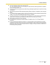
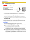
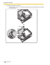
1. Loosen the screw.
2. Insert a grounding wire (user-supplied)*.
3. Tighten the screw.
4. Connect the grounding wire to ground.
* For grounding wire, green-and-yellow insulation is required, and the cross-sectional area of the
conductor must be more than 0.75 mm
2
or 18 AWG.
Screw
Grounding
wire
To ground