


4 February 2005 IPD4-A2-GZ40-00
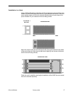
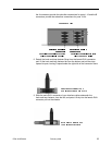
2 – Rack Mount Brackets (either 19" or 23", as ordered)
10 – #6 Phillips Bracket Screws
8 – #10 Phillips Rack Screws
8 – #12 Phillips Rack Screws
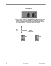
If there is visible damage, do not attempt to connect the device. Contact your sales
representative.
Installation Options
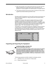
The 4000E BLC is designed for installation in a Restricted Access area where
admittance is limited to trained and authorized service personel. It may be
installed on a tabletop or in a rack.
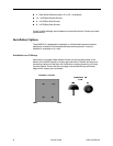
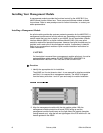
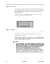
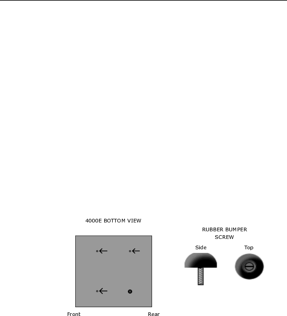
Installation on a Tabletop
Insert the four provided rubber bumper screws into the mounting holes at the
bottom of the 4000E chassis for surface grip and airflow. Position and secure all
connecting cables such that they will not become a tripping hazard or pull loose
from the chassis. Ensure that the air supply vents around the top and bottom
edges of the chassis are not blocked.