


IPD4-A2-GZ40-00 February 2005 11
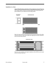
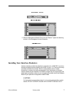
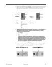
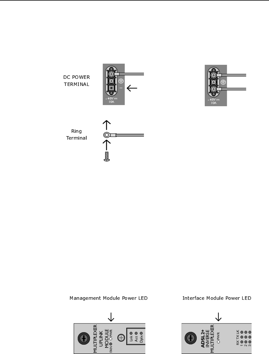
5. Remove the right-hand screw (labeled "–") from the same terminal block. Slide
the ring terminal of your NEGATIVE lead around the shaft of the screw and
insert the screw into the same "–" terminal from which it was removed.
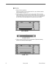
6. Connect both power leads to a fuse panel. The negative (–) lead connects to a
"Batt" (Battery) terminal and the positive (+) lead connects to a "Return"
terminal on your DC power supply.
CAUTION:
Observe proper polarity.
The power source(s) connected to the 4000E must be equipped with a
disconnect device such as an On/Off switch. Otherwise, an appropriately
rated circuit breaker must be installed on each power circuit to be used. In
the case of an emergency, hazardous voltages will not be removed from
the 4000E until all power sources have been either turned off or
disconnected from the chassis.
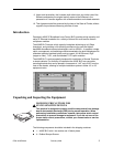
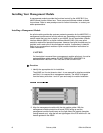
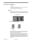
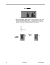
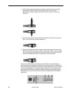
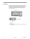
7. Turn your power source(s) on. The PWR (power) LED on both the interface
module and management module faceplates will illuminate solid green to
indicate the modules are receiving power.
Negative (–)
Termina l
NEGATIVE
POWER LEAD