


IP LDK-20 Installation Manual Board Installation
26
5-6 RESERVED
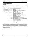
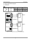
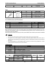
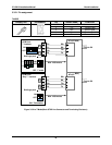
3.2.1.3 MJ4 Pin Assignment
MBUB
CONNECTOR PIN NUMBER NO SIGNAL NAME
1,2 Relay1-R, Relay1-T
3,4 Relay2-R, Relay2-T
5,6 EXT_PAGE-R, EXT_PAGE-T
RJ45
7,8 Alarm-R, Alarm-T
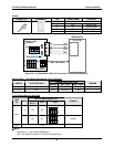
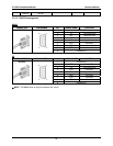
3.2.1.4 SW3 Functions and LED Indications
SWITCH FUNCTION OFF ON(DEFAULT)
3-1 Administration Programming Access Disable Enable
3-2 Command/Event Trace (The purpose of testing software) Enable Disable
3-3 SMDI (Simplified Message Desk Control –Voice Mail ) SMDI ON SMDI OFF
3-4 Database default on power up Disable Enable
Before programming the system, switch 3-4 should be placed in the ON position and power cycled-OFF and –ON to
initialize the system database to default. Once the database has been initialized, switch 3-4 should be placed in the
OFF position to protect the database.
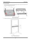
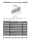
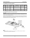
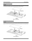
After putting the lithium battery switch (SW1) into ON to protect RAM/RTC data, install the option boards to the MBUB.
CAUTION
• The DIP switch, SW1 should be turned ON to protect system data in case of a power failure.
• The system will not function properly if the battery is incorrectly replaced. Replace only with the same or
equivalent type recommended by the manufacturer. Dispose of used batteries according to the manufacturer
instructions.
• The 4th pole (switch 4) of SW3 should be OFF to protect the features being programmed in Admin
programming after the system power up and initialization.
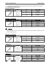
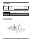
LED INDICATIONS
LED MEANING
LD1 (RED) Periodic toggle – ON: 2 sec., OFF: 100m sec.
LD2 (RED) Periodic toggle – ON: 2 sec., OFF: 100m sec.
LD3 (RED) Timer, Flashing every 100msec
LD4 (RED) LCD active updating, Flashing every 300msec
LD5 (GREEN) The status of PLL for 32Mhz clock synchronization (ON : ACT, OFF : INACT)
LD6 (RED) The status of Main SYSTEM Power
STATUS
LED
ON OFF
LINE NO. REMARK
RED ERROR
LD7
GREEN IN-USE
IDLE 1 BRI
LD8
RED ERROR
IDLE 2 BRI