


IP LDK-20 Installation Manual
i
T
T
A
A
B
B
L
L
E
E
O
O
F
F
C
C
O
O
N
N
T
T
E
E
N
N
T
T
S
S
■ IMPORTANT SAFETY INSTRUCTIONS ....................................................... 1
Safety requirements .................................................................................................................... 1
■ PRECAUTION................................................................................................. 2
■ THE STRUCTURE OF MANUAL ................................................................... 3
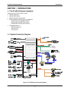
SECTION 1. INTRODUCTION................................................................................ 4
1.1 The IP LDK-20 System highlights......................................................................................... 4
1.2 System Connection Diagram............................................................................................... 4
1.3 System Components............................................................................................................ 5
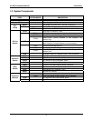
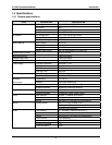
1.4 Specifications ....................................................................................................................... 6
1.4.1 General specifications.............................................................................................................. 6
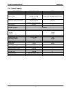
1.4.2 System Capacity ...................................................................................................................... 7
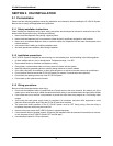
SECTION 2. KSU INSTALLATION ......................................................................... 8
2.1 Pre-Installation...................................................................................................................... 8
2.1.1 Safety installation instructions ................................................................................................. 8
2.1.2 Installation precautions ............................................................................................................ 8
2.1.3 Wiring precautions ................................................................................................................... 8
2.2 KSU Installation.................................................................................................................... 9
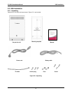
2.2.1 Unpacking ................................................................................................................................ 9
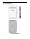
2.2.2 KSU exterior and dimension................................................................................................... 10
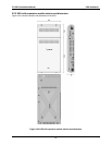
2.2.3 KSU with expansion module exterior and dimension............................................................. 11
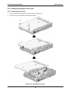
2.2.4 Opening and closing the front cover......................................................................................12
2.2.5 Frame ground connection...................................................................................................... 14
2.2.6 Power Supply Unit (PSU) installation .................................................................................... 15
2.2.7 External backup batteries installation.................................................................................... 16
2.2.8 KSU mounting........................................................................................................................ 17
SECTION 3. BOARD INSTALLATION.................................................................. 20
3.1 Installation of the Boards.................................................................................................... 20
3.2 MBUB (Main Board Unit) ................................................................................................... 21
3.2.1 Modular Jack(MJ1~MJ3) Pin Assignment............................................................................. 23
3.3 Installation of the CO Line Board....................................................................................... 29
3.3.1 LCOB (CID Loop Start CO line Interface Board)................................................................... 29
3.3.2 STIB (Basic Rate Interface Board: Selectable S/T interface) ............................................... 32
3.3.3 CBIB (CID Loop Start CO line + Basic Rate Interface Board) .............................................. 36
3.4 Installation of the Extension Board .................................................................................... 39
3.4.1 DTIB4 (Digital Terminal Interface Board) .............................................................................. 39
3.4.2 DTIB8 (Digital Terminal Interface Board) .............................................................................. 40
3.4.3 SLIB4 (Single Line Interface Board)......................................................................................41
3.4.4 SLIB8 (Single Line Interface Board)......................................................................................42
3.5 Other Board Installations.................................................................................................... 43
3.5.1 VMIBE (Voice Mail Interface Board Enhanced) .................................................................... 43
3.5.2 AAFBE(Auto Attendant Function Board Enhanced) ............................................................. 44
3.5.3 LANU (LAN interface Unit)..................................................................................................... 45
3.5.4 MODU (MODEM function Unit) ............................................................................................. 46
SECTION 4. EXPANSION MODULE INSTALLATION.......................................... 47