


SECTION 5 CIRCUIT DESCRIPTION
5 - 1
5-1 RECEIVER CIRCUITS
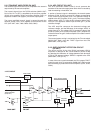
5-1-1 ANTENNA SWITCHING CIRCUIT (PA UNIT)
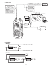
The antenna switching circuit toggles the receive (RX) line and
transmit (TX) line.
The received signals from the antenna are passed through the
low-pass filter (ANT UNIT; L801, L802, C802, C803, C807)
and antenna switch (D701, D704, D706).
While transmitting, the voltage on the T5V line is applied to
D701, D704 and D706, and these are ON. Thus the TX line
is connected to the antenna. Simultaneously, the RX line is
connected to the ground (GND) to prevent transmit signal
entering.
While receiving, no voltage is applied to the D701, D704 and
D706, and these are OFF. Thus the TX line and the antenna
are disconnected to prevent received signals entering.
Simultaneously, the RX line is disconnected from the GND and
the received signals are passed through the low-pass filter
(L712, L714, C750, C751). The fi ltered signals are applied to
the RF circuits.
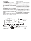
5-1-2 RF CIRCUITS (MAIN UNIT)
RF circuits filter and amplify the received signals within the
frequency coverage.
The received signals from the antenna switching circuit are
passed though the two-staged bandpass filter (BPF; D19,
D24, L7, L8, C22, C25, C27–C29, C369) to fi lter-out unwanted
signals, and the fi ltered signals are applied to the RF amplifi er
(Q5). The amplifi ed received signals are then applied to the 1st
mixer (Q6) via another BPF (L47–L49, C19, C40, C437–C439,
C443).
5-1-3 1st IF CIRCUITS (MAIN UNIT)
The received signals are converted into the 1st IF signal,
fi ltered and amplifi ed at the 1st IF circuits.
The received signals from the BPF (L47–L49, C19, C40, C437
–C439, C443) are applied to the 1st mixer (Q6) and converted
into the 46.35 MHz 1st IF signal by being mixed with the local
oscillator (LO) signal from the RX VCO (Q17, D9, D11, D33).
The converted 1st IF signal is passed through the 1st IF fi lter
(FI1) to filter-out adjacent signals, then applied to the 1st IF
amplifi er (Q7). The amplifi ed 1st IF signal is then applied to the
FM IF IC (IC9, pin 16).
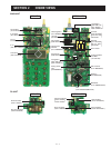
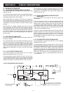
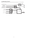
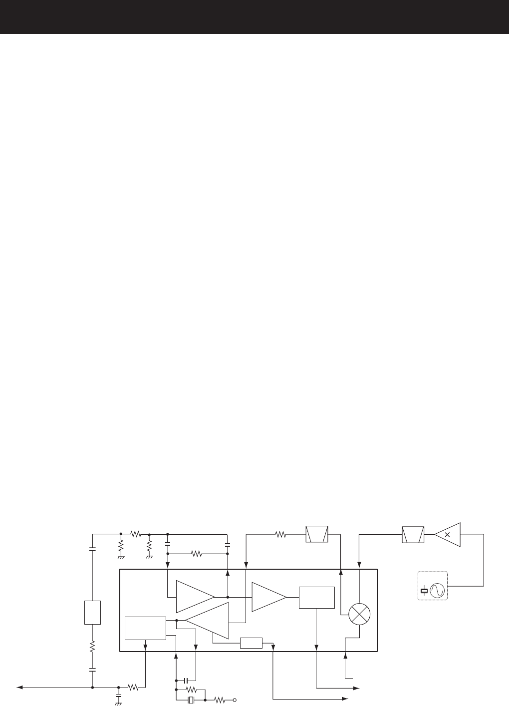
5-1-4 2nd IF AND DEMODULATOR CIRCUITS
(MAIN UNIT)
The 1st IF signal is converted into the 2nd IF signal, and
demodulated.
The 1st IF signal from the 1st IF amplifi er is applied to the 2nd
mixer in the FM IF IC (IC9, pin 16), and converted into the
450 kHz 2nd IF signal by being mixed with the 45.9 MHz 2nd
LO signal from the reference frequency oscillator (X2) via the
tripler (Q22) and BPF (L33, C163, C164, C166). The converted
2nd IF signal is output from pin 3, and passed through the 2nd
IF fi lters to remove sideband noise.
The 2nd IF signal is passed through the 2nd IF fi lter (FI2) and
applied to the FM IF IC (IC9, pin 5) again. The fi ltered 2nd IF
signal is amplifi ed at the limiter amplifi er, and FM-demodulated
by the quadrature detector (IC9, pins 10, 11, X1). The
demodulated AF signals are output from pin 9, then applied to
the AF amplifi er circuits.
5-1-5 AF AMPLIFIER CIRCUITS (MAIN UNIT)
The demodulated AF signals from the FM IF IC are amplifi ed
and fi ltered at AF circuits.
The demodulated AF signals from the FM IF IC (IC9, pin 9) are
passed through high-pass fi lter (HPF; IC5, pins 2, 1) to remove
tone signals. The filtered AF signals are passed through the
de-emphasis circuit (R142, C249) to obtain the 6 dB/oct of
frequency characteristic. The de-emphasized AF signals are
passed through the RX mute switch (Q32, Q33), AF switch
(Q36, Q37), HPF (IC5, pins 13, 14), analog switch (IC3, pins 1,
2), AF mixer (IC5, pins 6, 7) and analog switch (IC3, pins 10,
11) in sequence.
D/A converter
(IC12)
Mixer
RSSI
Quadrature
detector
24
23
1st IF signal from the 1st IF amplifier (Q7)
16
Noise
detector
R5V
X1
11 10
FM IF IC (IC9)
Filter
amp.
Noise
amp.
Limiter
amp.
Demodulated signals
to the AF circuits
9
“NOIS” signal to the CPU (IC22: pin 75)
“RSSI” signal to the CPU (IC22: pin 50)
13 12
Q22
X2
15.3 MHz
45.9 MHz
BPF
2
3
8
7 3 5
FI2
TCXO
• 2nd IF AND DEMODULATOR CIRCUITS