


6 - 5
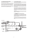
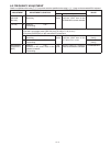
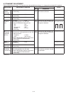
6-3 TRANSMIT ADJUSTMENT
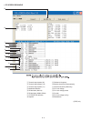
Select an adjustment item using [
↑
] / [
↓
] keys, then set to the specifi ed value using [
←
] / [
→
] keys on the connected PC’s keyboard.
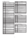
ADJUSTMENT ADJUSTMENT CONDITION
MEASUREMENT
VALUE
UNIT OPERATION
OUTPUT
POWER
[Power (Hi)]
1 • Channel
• Transmitting
: CH 3 Top
panel
Connect an RF power meter to
the antenna connector.
5.0 W
[Power (L2)] 2 • Channel
• Transmitting
: CH 4 2.0 W
[Power (L1)] 3 • Channel
• Transmitting
: CH 5 1.0 W
MODULATION
BALANCE
[BAL]
1 • Channel : CH 6 Top
panel
Connect the FM deviation me-
ter to the antenna connector
through an attenuator.
Set to square wave form
• No audio applied to the JIG cable.
• Set an FM deviation meter same as;
HPF
LPF
De-emphasis
Detector
: OFF
: 20 kHz
: OFF
: (P–P)/2
• Transmitting
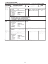
FM
DEVIATION
(NARROW)
[MOD N]
1
• Channel : CH 5
Top
panel
Connect the FM deviation me-
ter to the antenna connector
through an attenuator.
±2.05 to ±2.15 kHz
• Connect an audio generator to the JIG
cable and set as;
Frequency : 1.0 kHz
Level : 150 mV rms
• Set the FM deviation meter to same condi-
tion as “MODULATION BALANCE.”
• Transmitting
(WIDE)
[MOD ratio]
2
• Channel
• Transmitting
: CH 9
±4.05 to ±4.15 kHz
(MIDDLE)*
[MOD ratio]
3
• Channel
• Transmitting
: CH 7
±3.15 to ±3.25 kHz
CTCSS/DTCS
DEVIATION
[CTCS/DTCS]
1
• Channel : CH 8
Top
panel
Connect an FM deviation meter to
the antenna connector through
an attenuator.
±0.68 to
±
0.72 kHz
• No audio applied to the JIG cable.
• Set the FM deviation meter to same condi-
tion as “MODULATION BALANCE.”
• Transmitting
*; [EUR] only.