


5 - 3
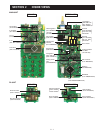
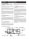
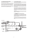
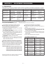
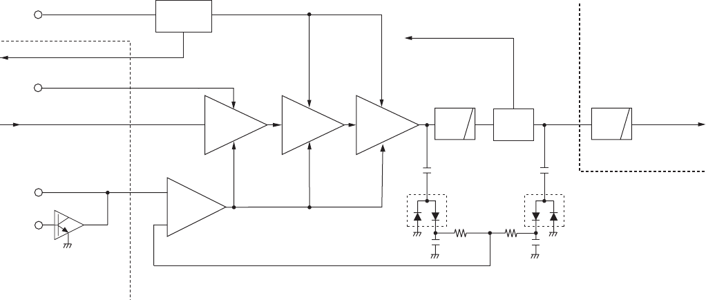
5-2-3 TRANSMIT AMPLIFIERS (PA UNIT)
The transmit signal from the VCO is amplifi ed to the transmit
output level by the transmit amplifi ers.
The transmit signal from the TX/RX switches (MAIN UNIT;
D16 is ON, D17 is OFF) is amplifi ed by the pre-drive amplifi er
(Q704), drive amplifi er (Q702) and power amplifi er (Q701) in
sequence to obtain 5 W (approx.) of transmit output power.
The power-amplified transmit signal is passed through the
antenna switch (D701), then applied to the antenna via the
LPF (ANT UNIT; L801, L802, C802, C803, C807).
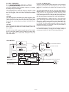
5-2-4 APC CIRCUIT (PA UNIT)
The APC (Automatic Power Control) circuit prevents the
transition of the transmit output power level which is caused by
load mismatching or heat effect, etc.
A portion of transmit signal is detected by the transmit power
detectors (D702, D703) to produce DC voltage corresponding
to the transmit output power level. The detected voltage is
applied to the APC amplifi er (IC701, pin 3). The transmit power
setting voltage “APC (T1)” from the D/A converter (MAIN UNIT;
IC23, pin 1) is applied to another input terminal (pin 1) as the
reference voltage.
The APC amplifier compares the detected voltage and
reference voltage, and the difference of the voltage “APCV” is
output from pin 4. The voltage “APCV” controls the bias of the
pre-drive (Q704), drive (Q702) and power (Q701) amplifi ers to
reduce/increase the gain of these amplifi ers for stable transmit
output power.
The transmit power muting is carried out by the TX mute switch
(MAIN UNIT; Q46), using the “TMUT” signal from the CPU
(MAIN UNIT; IC22, pin 35).
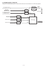
5-2-5 OVER CURRENT DETECTION CIRCUIT
(PA UNIT)
The driving current of the drive (Q702) and power (Q701)
amplifiers is detected at the current detector (Q705, Q706)
by detecting the difference of voltage between both terminals
of R714. The detected voltage “ISENS” is applied to the CPU
(MAIN UNIT; IC22, pin 47).
In case of the over current is detected, the CPU outputs “TMUT”
signal from pin 35 to TX mute switch (MAIN UNIT; Q46) to stop
the transmitting to protect the transmit amplifi ers (Q701, Q702,
Q704).
Power
amp.
APC
amp.
Drive
amp.
+
1
3
4
–
VCC
MAIN UNIT PA UNIT
to the antenna
T1
TMUT
Transmit signal from the
TX/RX switches
(D16, D17)
T5V
Q702
Q704
APCV
APC
P_DET
IC701
Q701
to the receiver circuits
LPF LPF
ANT
SW
D703
D702
D701
TX power
detectors
Q46
Pre-drive
amp.
ANT UNIT
Q705, Q706
Current
detector
ISENS
• APC CIRCUIT