


A part’s listing in this catalog does not guarantee its availability.
To download/print the most current catalog, go to www.lordfulfi llment.com/upload/PC7000.pdf. Rev.1 10/08
Page 106 of 124
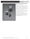
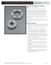
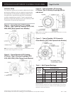
DYNAFLEX ELASTOMERIC FLEXIBLE COUPLINGS
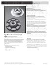
Dynafl ex LCR Series Couplings
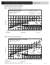
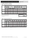
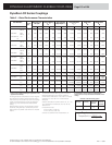
Table 1 – Specifi cations and Dimensions
Part Number
Rated Performance Characteristics
Torque
Rating
Per
100 rpm
Capacity
Static
Torsional
Rate - K
θ
Axial Rate
- K
A
Radial
Rate - K
R
Permissible Misalignments
lb-in N-m hp kW
1750 rpm 2000 rpm 3600 rpm
lb-in/
rad
N-m/
rad
lb/in
N/mm
lb/in
N/mm
Angular
Axial Parallel
hp kW hp kW hp kW in mm in mm
LCR-275-400-004A
125 14 0.20 0.15 3.5 2.6 4.0 3.0 7.1 5.3 420 47 150 26 375 66 ±5° ±1/8 3.18 ±1/16 1.59
LCR-275-400-009A
290 33 0.46 0.34 8.1 6.0 9.2 6.9 16.6 12.4 530 60 350 60 850 149 ±4° ±3/32 2.38 ±1/16 1.59
LCR-275-400-017A
550 62 0.87 0.65 15.3 11.4 17.5 13.0 31.4 23.4 1600 181 950 166 1300 228 ±3° ±3/64 1.19 ±1/32 0.79
LCR-300-600-046A
1440 163 2.28 1.70 40.0 29.8 45.7 34.1 82.3 61.3 18000 2034 2300 404 4500 790 ±2° ±1/16 1.59 ±1/32 0.79
LCR-400-800-060A
1900 215 3.01 2.24 52.8 39.3 60.3 45.0 108.5 80.9 24000 2712 1450 254 3000 525 ±2° ±1/16 1.59 ±1/64 0.40
LCR-400-800-115A
3600 407 5.71 4.26 100.0 74.5 114.2 85.2 205.6 153.3 46000 5197 3600 630 6400 1121 ±2° ±1/16 1.59 ±1/64 0.40
LCR-400-800-135A
4200 475 6.66 4.97 116.6 87.0 133.3 99.4 239.9 178.9 63000 7118 4200 736 9000 1576 ±1-1/2° ±1/16 1.59 ±1/64 0.40
LCR-450-600-011A
350 40 0.56 0.42 9.6 7.1 11.1 8.3 20.0 14.9 3100 350 1000 175 420 74 ±5° ±1/8 3.18 ±1/16 1.59
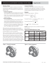
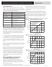
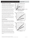
Torque ratings as listed are maximum steady torques per
application requirements. For general applications, dynamic
torques of ±35 percent of the coupling rate torques can be
applied to the listed torque ratings. Shock torques (e.g.,
start-up torque, etc.) of up to 200 percent rated torque are
generally acceptable.
Torque Requirements:
Torque (lb-in) = 63025 x hp
rpm
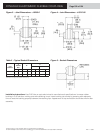
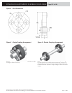
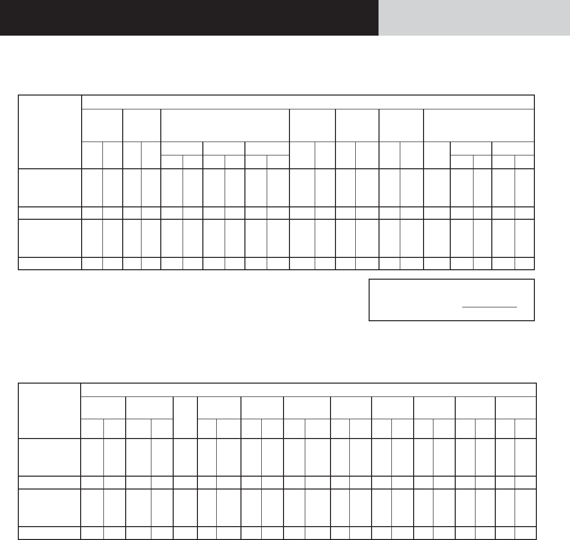
Table 2 – Specifi cations and Dimensions
Part Number
Physical Characteristics (Nominal)*
Weight
Inertia
No. of
Inserts
A
B.C. Dia.
B
Hole Dia.
C
Coupling I.D.
D
Coupling I.D.
E
Length
F
Insert Dia.
G
Length
H
Length
lb-
Mass
kg
lb-in-
sec
2
kg-
mm
2
in mm in mm in mm in mm in mm in mm in mm in mm
LCR-275-400-004A
0.52 0.236 0.0020 226.0 4 2.75 69.85 0.32 8.13 4.00 101.60 1.62 41.15 1.00 25.40 0.91 23.11 0.12 3.18 0.75 19.05
LCR-275-400-009A
0.52 0.236 0.0020 226.0 4 2.75 69.85 0.32 8.13 4.00 101.60 1.62 41.15 1.00 25.40 0.91 23.11 0.12 3.18 0.75 19.05
LCR-275-400-017A
1.00 0.454 0.0038 430.0 4 2.75 69.85 0.32 8.13 4.00 101.60 1.62 41.15 1.75 44.45 0.91 23.11 0.12 3.18 1.50 38.10
LCR-300-600-046A
0.91 0.413 0.0041 463.0 6 3.00 76.20 0.39 9.91 4.06 103.12 1.88 47.75 1.53 38.86 1.00 25.40 0.12 3.18 1.28 32.50
LCR-400-800-060A
1.25 0.567 0.0072 814.0 8 4.00 101.60 0.51 12.95 5.21 132.33 2.74 69.60 1.50 38.10 1.00 25.40 0.12 3.18 1.25 31.75
LCR-400-800-115A
1.25 0.567 0.0072 814.0 8 4.00 101.60 0.51 12.95 5.21 132.33 2.74 69.60 1.50 38.10 1.00 25.40 0.12 3.18 1.25 31.75
LCR-400-800-135A
1.40 0.635 0.0099 111.9 8 4.00 101.60 0.51 12.95 5.21 132.33 2.74 69.60 2.00 50.80 1.00 25.40 0.12 3.18 1.75 44.45
LCR-450-600-011A
0.78 0.354 0.0032 362.0 6 4.50 114.30 0.41 10.30 5.56 141.22 3.40 86.36 0.68 17.27 1.00 25.40 0.12 3.18 0.43 10.92
* See detail drawings by part number for tolerances.
Does not include bolts or fl anges.
LORD does not supply hubs. LORD supplies ring
elements only.