


3
0
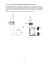
3.1.6 Postal Switch
This programming sequence will set how the two switch inputs on the telephone entry system control
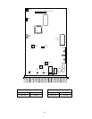
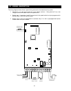
board will operate. Switch input 1 is labeled PSW (postal switch) and is found on terminal 4 of the
main terminal strip. Switch input 2 is a two terminal auxiliary input located on the upper left hand
corner of the control board. These switch inputs can be programmed to activate their respective
relays (switch 1 - relay 1, switch 2 - relay 2). They can also be programmed so that switch 1 dials out
the phone number programmed in directory code 0, 00, 000, or 0000, and switch 2 dials out the
phone number programmed in directory code 1, 01, 001, or 0001. Each switch is programmed
independently.
1. Press and enter the four-digit MASTER CODE (beep).
2. Press (beep) to set switch 1,
or
press (beep) to set switch 2.
3. Press (beep) to set the switch input to activate the relay,
or
press (beep) to
set the switch input to dial-out a preprogrammed phone number.
4. Press
TOGETHER to end this programming step (beeeeeep).
3.1.7 Touch-tone / Rotary-dial
This programming sequence will set the telephone entry system to dial out in either a touch-tone or
rotary format. Generally, this will be set for touch-tone.
Factory setting =
touch-tone
.
1. Press and enter the four digit MASTER CODE (beep).
2. Enter (beep) for touch-tone
or
enter (beep) for rotary.
3. Press TOGETHER to end this programming step (beeeeeep).
3.1.8 Number of Rings to Answer
This programming sequence sets the number of rings to allow before the telephone entry system
answers a call placed to it. This programming sequence does not affect the number of times that a
resident’s telephone will ring when a call is placed from the entry system to the resident.
1. Press and enter the four-digit MASTER CODE (beep).
2. Enter the number of rings then press (beep).
3. Press TOGETHER to end this programming step (beeeeeep).