


2
4
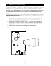
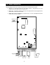
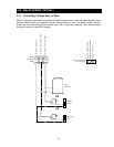
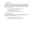
The wiring diagram below shows a typical wiring scheme for the telephone entry system.
•
Terminal 3 is a case ground and not a low voltage common. Using terminal 3 as a low
voltage common will cause noise on the phone line.
•
Switch input 1 (terminals 4 and 8) is pre-wired to the postal switch and pre-programmed to
activate relay 1 when the input is closed.
•
Switch input 2 can be programmed to activate relay 2 or dial a preprogrammed phone
number when the input is closed.
2.2 WIRING DESCRIPTION
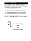
1 141312111098765432
Normally Open
Switch 2 Input
Central Office
Phone Line
Earth Ground
Only
Normally Open
Switch 1 Input
12 Volt
Battery
16 VAC, 20 VA
Transformer
+