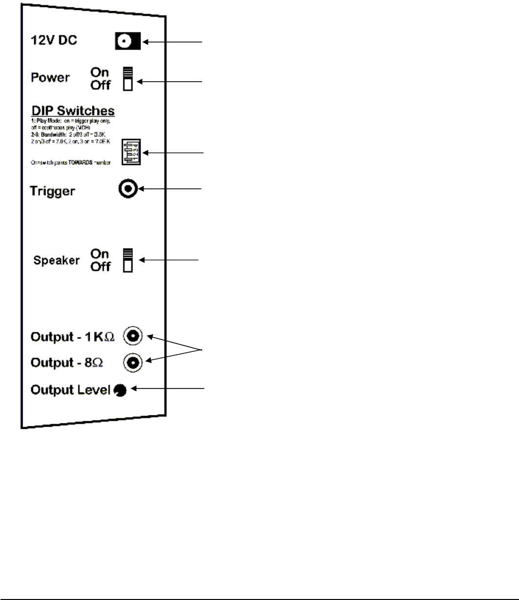
Connections Panel
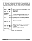
The left side panel is where the connectors are for external equipment including
the power supply, the phone system that receives the SoundBrick's output, and
the optional external trigger cable. Also located here are the volume (level)
control, the main power switch, the internal speaker switch, and the option select
(DIP) switches.
Power supply connector (12VDC, 500mA, center
pin positive
)
Power switch
3 option select (“DIP”) switches, used to set
continuous or trigger mode and bandwidth.
Connector for the 1/8” mini-plug trigger cable
(optional part) for remote message activation
Internal speaker switch
RCA connectors for audio output. Separate 8Ω
and 1KΩ outputs provided for impedance
matching.
Output level adjustment knob
Figure 2 - Side Panel Diagram
SoundBrick 500 01/08/2001
7


