


10
Ether
net connections (AEW-R5200):
An RJ-45 jack on the
rear panel of each AEW-R5200 provides an Ethernet 10 BaseT
data/control connection from both of its channels to an external
computer system. Data monitored includes actual, real-time
“
RF” and “AF” levels for receiver channels with direct Ethernet
connections to the associated computer. All other linked
receivers in a system supply control-function access and all their
data – except for “
RF” and “AF” levels – to the
computer connected to the Master receiver.
Multiple AEW
-R5200 receivers in a system can each provide
r
eal-time “
RF” and “AF” levels to the associated computer if
each AEW
-R5200 has its own Ethernet connection, through an
Ethernet hub, to the computer.
Other than being able to “see” the “
RF” and “AF” levels, all
functions of all r
eceivers in a linked system can be
monitor
ed and controlled from the computer connected to the
Master r
eceiver.
Details of the computer setup and operation will be found in
a separate AEW Control Interface manual provided with
AEW-R5200 receivers and 5000 Series systems.
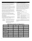
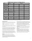
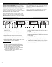
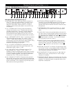
Receiver Installation (Continued)
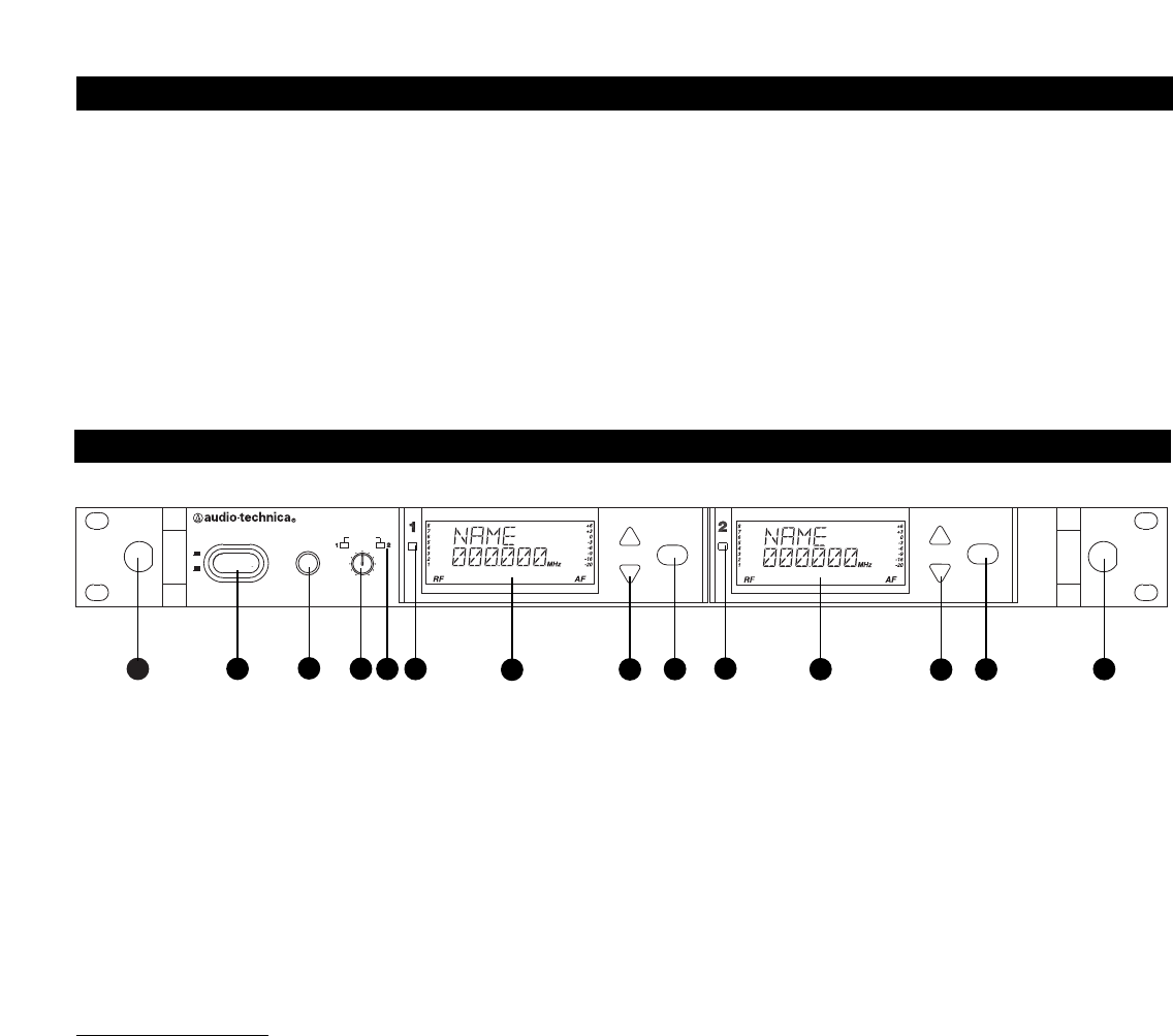
6 / 10 LCD WINDOW: Liquid Crystal Display indicates control
settings and operational readings. See Figure G on page 13
for details.
7 / 11 UP/DOWN BUTTONS: Press Up or Down arrow
button, in conjunction with the Mode/Set button, to step
through menus, select operating frequency and edit receiver
function choices.
8 / 12 MODE/SET BUTTON: Use in conjunction with the
Up/Down arrow buttons to step through menus, choose
operating frequency and select receiver function options.
13 FRONT-MOUNT ANTENNAS: Cables and panel connectors
are included with the AEW-R5200 to permit attaching
antennas at the front panel.
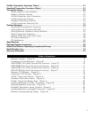
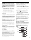
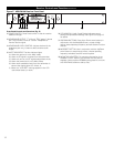
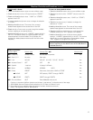
Front Panel Controls and Functions (Fig. C)
1 POWER SWITCH: Press Power switch in and the receiver
readouts will light.
2 HEADPHONE OUTPUT:
1
/
4
" (6.3 mm) TRS (“stereo”) phone
jack. Plug in either a mono or "stereo" headphone to monitor
receiver signal.
3 HEADPHONE LEVEL CONTROL / CHANNEL SWITCH:
Adjusts the level of the headphone jack only; it does not
affect receiver audio output. Press-and-release the knob to
switch between Channel 1 and Channel 2.
4 HEADPHONE CHANNEL INDICATOR: Shows which receiver
channel is feeding the monitor headphones.
Channel 1 / Channel 2
5 / 9 ALER
T INDICA
TOR: The Aler
t Indicator lights:
(a) When the receiver is in the Mute mode,
(b) When no RF signal is r
eceived fr
om the transmitter
,
(c) When only one or two RF signal-str
ength bars are on,
(d) When the transmitter is in the Mute mode,
(e) When audio modulation level from the transmitter is
close to the clipping point (AF +6 bar), or
(f) When the “LOW BAT” warning appears in the LCD
(transmitter batter
y is weak).
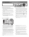
Receiver Controls and Functions
Figure C AEW-R5200 Receiver Front Panel
POWER
ON
OFF
MODE/SET
MODE/SET
OUTPUT
PHONES
UHF SYNTHESIZED DIVERSITY RECEIVER AEW
-R5200
MIN MAX
PUSH SEL
LEVEL
RX NAME
RX NAME
13
3
6
7
2
1
4 5
8
9
10
11
12
13