


13
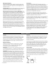
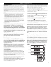
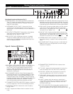
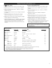
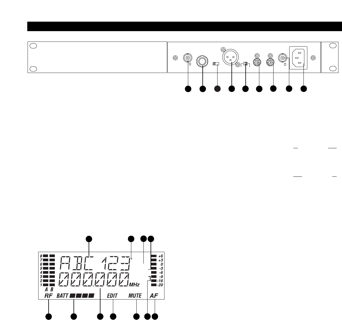
Figure F AEW-R4100 Receiver Rear Panel
IN
OUTPUT
(UNBAL.)
INSTR
UMENT
0/-6/-12
A
TTN (dB)
BALANCED
MIC OUTPUT
GROUND
LIFT
GROUND IN
–
LINK
–
OUT
IN
ANT. A
WARNING:
THIS APPARATUS MUST BE EARTHED.
A
C
˜
100V-240V
50/60Hz
ANT
. B
42
47
44
43
45
46
48
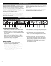
Rear Panel Controls and Functions (Fig. F)
40
ANTENNA INPUT JACK: BNC-type antenna connector for
T
uner “B.” Attach the antenna directly, or extend it with a
low-loss antenna cable. See the “Antennas” section on
page 8 for more details.
41 INSTRUMENT OUTPUT JACK:
1
/
4
" phone jack. Can be
connected to an aux-level input of a mixer, guitar amp or
tape recorder. On the AEW-R4100, this is an unbalanced TS
phone jack.
42 AF OUTPUT ATTENUATOR: Three-position switch adjusts
audio output level of both audio output jacks with
attenuation of 0 dB, –6 dB or –12 dB.
43 MIC OUTPUT JACK: XLRM-type connector. A standard
2-conductor shielded cable can be used to connect the
receiver output to a balanced microphone-level input on a
mixer or integrated amplifier.
44
GROUND LIFT SWITCH: Disconnects the ground pin of the
balanced output jack (43) from ground. Normally, the switch
should be to the right (ground connected). If hum caused by
a ground loop occurs, slide switch to the left (ground lifted).
45 LINK IN JACK: Connect provided cable to this jack with the
index mark on the plug aligned toward the screw head
above the jack. The r
eceiver with a Link In
and no Link Out
connection is the “Master” unit.
46 LINK OUT JACK: Connect provided cable to this jack with
the index mark on the plug aligned toward the screw head
above the jack. The receiver with a Link Out
and no Link In
connection is the last unit in a multi-unit system.
47 ANTENNA INPUT JACK: Connector for Tuner “A.” Attach
the antenna directly, or extend it with a low-loss antenna
cable.
48 AC POWER INPUT: IEC-type connector for 100V–240V AC,
50/60 Hz power input. No adjustment for mains voltage/
frequency is necessary.
Receiver Controls and Functions (Continued)
4140
RX NAME
RX LOCK
TX LO
TX HI
TX LOCK
TX NAME
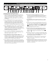
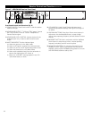
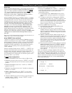
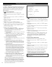
Figure G Receiver LCD Window
49
51 53 58 5952 57
54
50
56
55
49
RF SIGNAL LEVEL INDICA
TOR: Shows the strength of the
RF signal received from the transmitter. Also indicates
which Tuner (A or B) has the better reception and is in
operation. When the METER HOLD function is on, the
lowest-level RF signal received from the transmitter is
indicated by a flashing bar.
50 ALPHANUMERIC DISPLAY: Shows Receiver Name (57),
Transmitter Name (57), or Link Address (MASTER, or SLV
and the slave number). The factor
y setting displays “DEF”
in Receiver Name mode (“RX NAME”). Once the settings
have been changed, the unit will display the last setting and
mode selected. Also flashes the “
LOW.BAT” warning
when the associated transmitter’s batteries are weak.
51 TRANSMITTER
BA
TTER
Y INDICATOR: Displays a maximum
of four bar segments, with four bars indicating full power
.
52 FREQUENCY DISPLAY: Indicates the current frequency
setting in MHz.
53 “
EDIT”: Appears and flashes when the receiver is in edit
mode.
54
TRANSMITTER
RF
POWER
DISPLAY: Indicates either
“
TX LO” or “TX HI”.
55 “
TX LOCK”: Appears when the transmitter is in one of its
three lock settings (
ALL.LOC, MUT.LOC or PWR.LOC).
56
“
RX
LOCK
”: Appears when the r
eceiver is in one of its
thr
ee lock settings (
ALL.LOC, PC.LOC or RX.LOC).
57 TX/RX NAME: Indicates whether the transmitter name or
the receiver name is displaying in the top line of the LCD
display.
58
“
MUTE”: Appears when the r
eceiver or transmitter is
muted, when the r
eceiver is not r
eceiving an audio signal,
or when the r
eceiver is externally muted by use of the
EXTERNAL MUTE jack.
59 AF LEVEL INDICATOR: Shows the audio modulation level of
the received signal. When the METER HOLD function is on,
the bar cor
r
esponding to the highest level reached will stay
lit.