


Transmitter Controls and Functions (Continued)
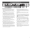
Audio Input Selector
The UniPak
™
body-pack transmitter provides input connections
for both low-impedance (Lo-Z) microphones and high-
impedance (Hi-Z) instruments. A wide range of Audio-Technica
Wireless Essentials
®
microphones and cables is available
pre-terminated with the appropriate professional latching
connector
. (See page 28.)
Selection of the desir
ed input – microphone or instrument – is
made thr
ough the function menu. Depending upon the input
selected, a small “
MIC” or “INST” will continue to show in
the LCD window, just below the frequency. (In the handheld
transmitters, “
MIC” will always show in the LCD window.)
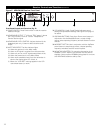
Setting Audio Input Level
AEW-T1000 UniPak: A 10-position audio input gain setting,
selected through the function menu, serves to match the audio
input level to the transmitter for best modulation with minimum
distortion. Available choices are +12 dB to –6 dB in 2 dB steps.
The default value is +6 dB.
AEW-T4100 and AEW-T6100 Dynamic Handhelds:
A 4-position audio input gain setting, selected through the
function menu, serves to match the audio input level to the
transmitter for best modulation with minimum distortion.
Available choices are +12 dB to –6 dB in 6 dB steps. The
default value is +6 dB.
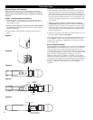
AEW-T3300 and AEW-T5400 Condenser Handhelds:
A 3-position audio input gain setting, selected through the
function menu, serves to match the audio input level to the
transmitter for best modulation with minimum distortion.
Available choices are +12 dB, +6 dB and 0 dB. The default
value is +6 dB. In addition, a mechanical pad switch on the
condenser capsule (inside the screw-on wire mesh grille) can
provide another 6 dB of attenuation. For best performance,
adjust the input level using the function menu choices, keeping
the capsule’s mechanical switch at 0 dB. If more audio attenua-
tion is needed than the menu provides, then set the capsule’s
pad switch to –6 dB.
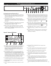
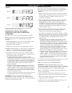
For all transmitters: Select the highest audio level setting that
does not result in over-modulation with the highest audio/
instr
ument input levels (an AF indication on the receiver no
higher than “+3”); watch the r
eceiver’
s “
AF” meter “+6”
indication and the Alert light to make certain they are not
triggered often by the highest audio levels.
The transmitter’s red LED power indicator, which is on during
normal operation, will blink
off if the peak audio input reaches
overload level.
Power/Mute Locks
Pr
ogrammable Power/Mute Locks limit the functioning of the
Power/Mute button as desir
ed for particular users and/or
applications. Power can be locked On; Mute can be locked
Off. Selection of the desired locks, if any, is made through the
function menu:
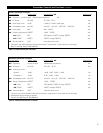
Setting
Description
NO.LOC The normal Power and Mute functions are
fully operational.
ALL.LOC Power is locked On and Mute is locked Off
when “
ALL.LOC” is applied. When in the
ALL.LOC mode, the transmitter may be
turned off by (1) re-accessing the
.LOC
Menu and changing the setting, (2) pressing
and holding the Up arrow button
and the Set
button
at the same time, until the power
goes off, or (3) removing and re-installing
the batteries. When the transmitter is tur
ned
on again, it will power up in the
NO.LOC
mode.
MUT.LOC In this mode, the audio cannot be muted
(Mute function is locked Off). The Power
functioning is unaffected.
“Mute” Note: If
ALL.LOC or MUT.LOC is
applied
while the transmitter is muted,
pressing the Power/Mute button once will
return the transmitter to un-muted operation;
thereafter the Mute function is disabled
(Mute Off) until the .LOC setting is changed
again.
PWR.LOC Power is locked On when “PWR.LOC” is
applied. The Mute functioning is unaffected.
When in the
PWR.LOC mode, the transmitter
may be turned off by: (1) Re-accessing the
.LOC Menu and changing the setting,
(2) Pressing and holding the Up arrow button
and the Set button at the same time, until
the power goes off, or (3) Removing and
re-installing the batteries. When the
transmitter is tur
ned on again, it will power
up in the
NO.LOC mode.
Note: Only the
ALL.LOC or PWR.LOC Power
function will change when batteries are
removed;
NO.LOC and MUT.LOC settings
remain stored in memory.
If an action is attempted that cur
r
ently is locked out, the
transmitter LCD will briefly display “
LOC.KED”, then return to
its previously displayed contents.
Whenever any lock condition is applied to a transmitter, its
associated
receiver will display a small “TX LOCK” in the LCD
window
, just to the right of the fr
equency
.
19