


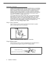

An Example System Setup
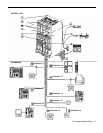
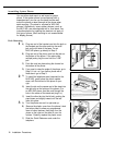
The next page shows a control unit with two 206 modules and
two 400 modules, giving the system a capacity of 12 outside
lines and 12 extensions. Although your system may differ, this
example will give you an idea of the types of equipment you
can connect to it. In the example, system phones and
industry-standard devices are connected to nine extensions.
The circled numbers in the figure refer to the following list,
which gives a brief description of the system’s hardware
components.
Control Unit
The control unit consists of these components:
Backplane. The backplane channels power to the
system and connects the system modules.
206 Modules. Each 206 module has jacks for two lines
and six extensions.
400 Modules. Each 400 module provides four line jacks
but no extensions. Notice that the 400 modules are
installed to the right of the 206 modules.
Processor Module. The processor module contains the
software that provides the system’s features. It also has
PAGE, SMDR, and MUSIC ON HOLD jacks.
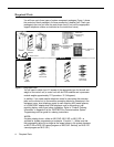
PAGE Jack. A loudspeaker paging system plugs
directly into this modular jack. The system is compatible
with any AT&T paging system, including the AT&T
PagePac6® shown here.
If you use equipment that rebroadcasts music or other
copyrighted materials, you may be required to obtain a
license from a third party such as ASCAP or BMI. Or you
can purchase a Magic On Hold system from AT&T,
which does not required you to obtain such as license.
SMDR Jack. A call reporting (or SMDR–Station
Message Detail Recording) device connects directly to
this jack. AT&T’s Call Accounting Terminal serial printer
and box are shown here.
MUSIC ON HOLD Jack. AT&T’s Magic on Hold® is
connected to this jack to provide customized music and
messages for callers on hold. Other types of audio
equipment (including a CD player, cassette player, or
stereo receiver) can be connected using an audio cord
with an RCA phono plug (not supplied).
Line Jacks. The top two jacks on each 206 module, and
all four jacks on each 400 module, connect to outside
telephone lines.
Extension Jacks. The bottom six jacks on each 206
module connect inside wiring for telephones and other
telecommunications equipment.
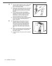
Network Interface Jacks. These jacks provide access
to telephone lines from the local telephone company.
Each outside line is connected to the system by
plugglng one end of the line cord into one of these jacks,
and the other end into a Iine jack on a 206 or 400 module.
Extensions
Various devices—including system phones and industry-
standard devices—can be connected to the modular wall
jacks. The modular wall jacks connect to the extension jacks
in the control unit by way of the building’s inside wiring.
Extension 10: These devices are connected:
■
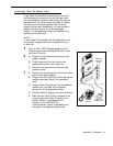
MLS-34D Display Phone. Typically, the receptionist
on programming extension 10 has an MLS-34D
display phone like the one shown here. The display
shows the time, dialed numbers, the duration of calls,
and programming messages.
An MLS-34D, MLS-18D, or MLS-12D is required for
system programming at extension 10 or 11, or both.
Use an MLS-18D only if there are no MLS-34D phones
in the system. Similarly, use an MLS-12D only if there
are no MLS-34D or MLS-18D phones in the system.
■
Call Assistant™ Intercom Autodialer. An Intercom
Autodialer is connected to the phone, for dialing
extensions and transferring calls to them with one
touch and for seeing which extensions are busy.
■
Standard Touch-Tone Phone. During a power
failure, the MLS-34D phone on extension 10 will not
work, but the receptionist can use the standard phone
to place and receive calls on line 1.
Extension 11: MLS-34D Display Phone. Another
MLS-34D is connected to programming extension 11.
This means you can program the system from this
extension while the receptionist at extension 10 is free to
handle calls.
Extension 12: MLS-18D Phone and Answering
Machine. An MLS-18D phone and an answering
machine are connected to this extension.
Extension 13: Standard Phone. A standard phone
(such as you might have in your home) is connected
directly to the extension jack.
Extension 14: Doorphone. A doorphone is installed at
the building entrance. When someone at the entrance
presses the button on the doorphone, the designated
extensions in the office ring automatically. (Any number
of extensions can be designated as doorphone alert
extensions.)
Extension 15: Bell. A loud bell is connected directly to
this extension jack. Any line programmed to ring on
extension 15 activates the loud bell—to alert users of an
incoming call in a large area, such as a warehouse.
Extension 16: MLS-12D Display Phone. This display
phone can handle 10 outside lines.
Extension 17: Fax Machine and Standard Phone. A
fax machine and standard phone share this extension.
This lets you have the use of another phone when the fax
machine is idle. (You can use a system phone at
another extension to monitor fax machine activity—see
“Fax Management Feature” of “Using Fax Machines” in
Chapter 4 of the PARTNER Plus Communications System
Programming and Use guide.)
Extension 18: MLC-6 Cordless Phone. An AT&T
MLC-6 cordless phone is connected to this extension. It
works like the corded MLS-6 system phone.
2
An Example System Setup