


Connecting Caller ID Display Units
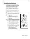
To get Caller ID information for an extension, you must
first subscribe to the service (on a per-line basis) from
your local telephone company, then connect the units as
described here. You must connect the Caller ID display
unit directly to the line that supports Caller ID at the
network interface jack. Additionally, you must provide a
separate wiring run for the unit to the appropriate
location. To have additional wiring runs installed, call a
qualified service technician.
NOTE:
To have Caller ID for multiple lines at a single phone, you
must provide a separate box and a separate wiring run
for each line.
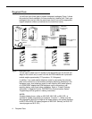
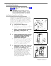
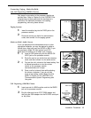
1
Insert an AT&T 267F2 bridging adapter into the
network interface jack associated with the line that
has Caller ID service.
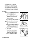
2
B)
C)
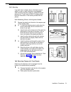
3
A)
B)
C)
D)
E)
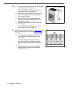
A)
Plug one end of a line cord into a jack on the
bridging adapter.
Plug the free end of the line cord into the
appropriate line jack in the control unit.
Route the cord as you did for other line and
extension cords.
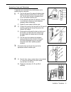
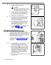
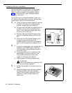
Plug one end of a second line cord into the other
jack on the bridging adapter.
Plug the free end of the cord into the appropriate
modular connecting block in the equipment
room.
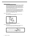
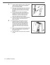
Plug the Caller ID display unit into the additional
modular jack—provided by the separate
wiring run—at the appropriate location.
Place the Caller ID display unit next to the phone.
Make sure the Caller ID line is assigned to the
extension where the Caller ID display unit is
located. Refer to “Line Assignment” in
Chapter 5 of the PARTNER Plus
Communications System Programming and
Use guide for programming instructions.
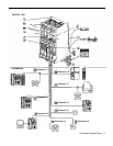
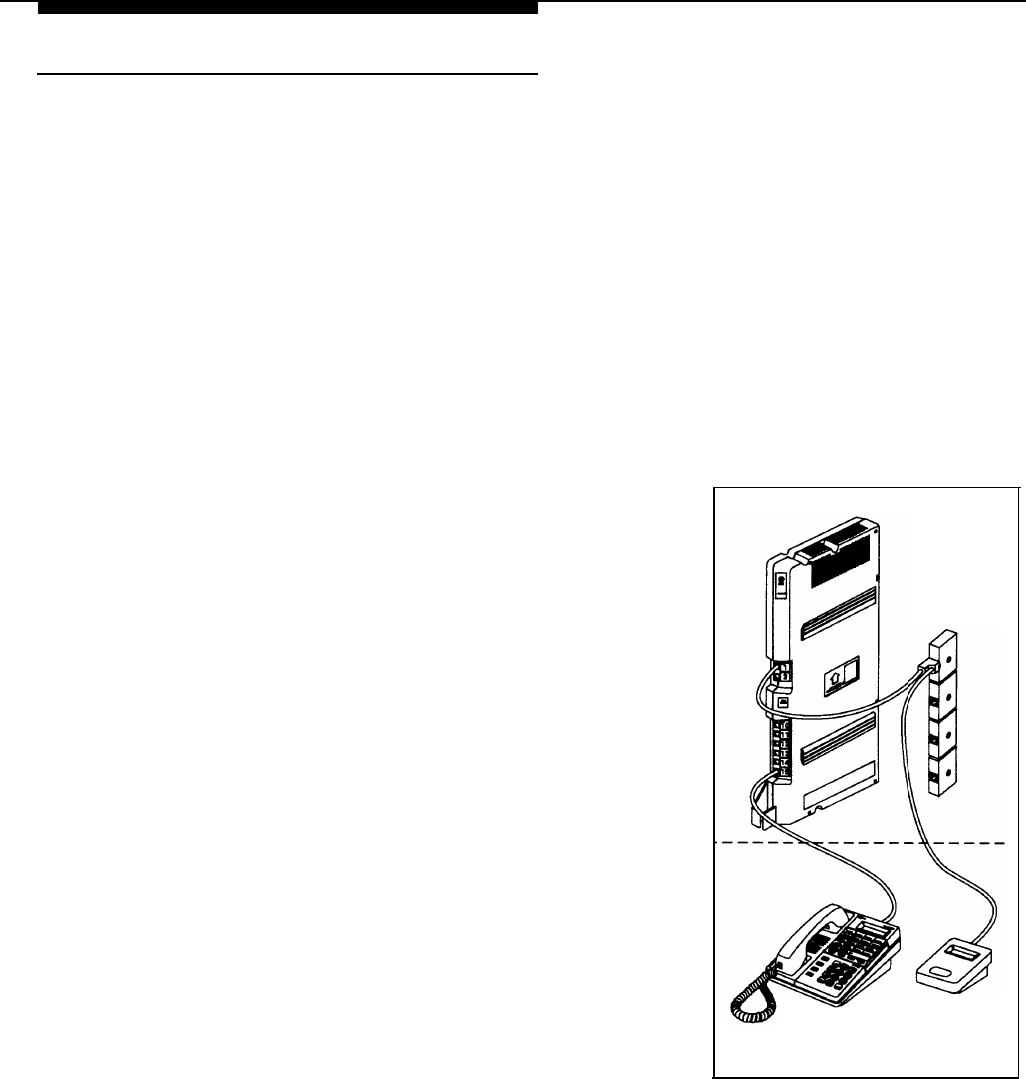
Network
Interface
Jacks
System
Phone
Caller ID
Display Unit
Installation Procedures
11