


■
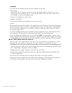
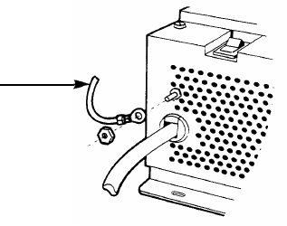
STEP 5 ATTACH THE GROUNDING WIRE.
The grounding wire must be attached to both power supplies to ensure lightning protection. Anchor
one end of the grounding wire to the grounding stud located by the power cord on each of the
power supplies.
Grounding
Wire
■
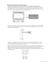
STEP 6 INSTALL LINE AND STATION CARDS.
If you purchased additional line and/or station cards, install them into the controller or expansion
unit following the instructions provided with the cards.
Specific instructions for Steps 7 through 14 are located in the 1224 Controller Customer Installation
■
■
Instructions.
STEP 7 TEST
Refer to Part
STEP 8 TEST
Refer to Part
INCOMING TELEPHONE LINES.
D of Step 2.
THE MAIN CONTROLLER AND EXPANSION UNIT.
E of Step 2.
■ STEP 9 CONNECT TELEPHONE LINES TO CONTROLLER AND/OR EXPANSION UNIT.
Refer to Part F of Step 2.
■ STEP 10 COMPLETE WIRING RUNS.
Refer to Step 3.
■ STEP 11 INSTALL TELEPHONES.
Refer to Step 4.
■ STEP 12 CONNECT MAIN CONTROLLER AND/OR EXPANSION UNIT TO WIRING RUNS.
Refer to Step 5.
■ STEP 13 INSTALL OPTIONAL EQUIPMENT.
Refer to Step 6.
■ STEP 14 PUT THE PANEL BACK ON.
Refer to Step 7.
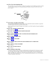
■ STEP 15 POWER UP THE SYSTEM.
To turn the system on, turn on the power switch located on the bottom left of each power supply
unit. The green LEDs will light. If either of the LEDs does not light, make sure that the power
supply is plugged into a working AC outlet that is not controlled by a switch. If it still does not
light or there are other problems, refer to the Troubleshooting information in your 1224 Controller
Customer Installation Instructions.
Expansion Unit Installation 5