


Introduction
This manual will show you how to install the SPIRIT
®
2448 Expansion Unit with your SPIRIT
Communications System. Please read the instructions carefully before beginning installation.
Instructions for installing wiring runs and telephones are part of the installation manual
provided with the SPIRIT 1224 Controller.
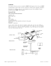
Overview Of Unit
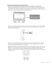
What You Should Find in
the Boxes
expansion unit
power supply unit
brace
strap
six ½” screws
4-foot grounding wire
System Directory Label (attached to the back of the panel)
label sheets
Installation Instructions
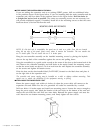
If your network interface jack (where the telephone company lines come into your building or
office has two lines on a single jack you should purchase a 267C adapter and a line cord (D4BU)
from your phone store or from your AT&T representative. If you need longer line and telephone
cords, you should purchase them also.
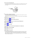
Expansion
Power Supply
Unit
Main
Power Supply
Unit
Grounding
Wire
CONTROLLER SECTION
AC Outlet
(standard 120 VAC)
AC Outlet
(standard 120 VAC)
Network Interface Jack
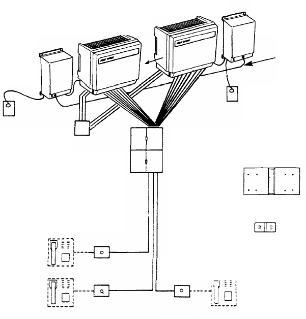
WIRING RUN SECTION
jumper cords
plugged into the
jak field and into
the control unit
a jack field installed
near your control
unit location
cable extending from
the jack field to each
telephone location
Brace
Strap
TELEPHONE SET SECTION
a modular connecting block at the end
of each cable (telephones will be
plugged in later)
SPIRIT is a registered trademark of AT&T
Expansion Unit Installation 1