


Installation
You will need the following to mount your controller on the wall:
• eight screws
For drywall, tile, or masonry use size 6 to 8 x
¾ inch plastic anchors with size 6 x 1 inch
slotted screws. For wood, use size 6 x 1 inch slotted round head wood screws. These screws
are available at your local hardware store.
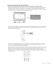
• 36-inch rule (yardstick or meter stick)
• flathead screwdriver
• drill with the drill bit recommended for the type of screws
• pencil
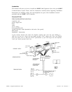
The expansion unit will be mounted to the right of the main controller. The power supply units
should be located within five feet of a grounded (three prong) AC outlet that is not controlled
by a switch. Each controller must be within six inches of where the power cable will connect
to its power supply unit.
If you are installing both the main controller and the expansion unit you will need four feet of
free wall space. The instructions for this begin with Step 2; you should skip Step 1.
If you are adding the expansion unit to your existing SPIRIT Communications System, there
must be adequate room (at least two feet) for the expansion unit and power supply unit. If there
is not adequate room to the right of the main controller, the main controller must be relocated.
■
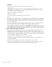
STEP 1 REMOVE MAIN CONTROLLER FROM WALL.
NOTE: If there is not enough slack in the cords so that the controller can be placed on a surface
away from the wall, remove the panel from the main controller and disconnect all cords.
CAUTION: Be sure all cords are marked so that they can be reconnected to the appropriate jacks.
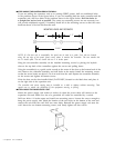
• Turn off the power switch on the power supply unit of the main controller (green LED will go
off.) Customization information will be retained.
• Unplug the power supply unit power cord from the AC outlet.
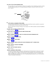
• At the power supply unit, disconnect the power cable that connects the main controller with
its power supply unit.
• Loosen the two mounting screws located at the bottom of the main controller.
• Remove the main controller from the wall by gently lifting up. Place the main controller on a
flat surface with adequate room for both the main and expansion controllers.
2 Expansion Unit Installation