- 6 -
EnglishFrançaisNederlands
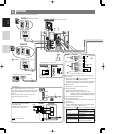
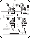
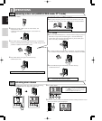
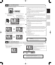
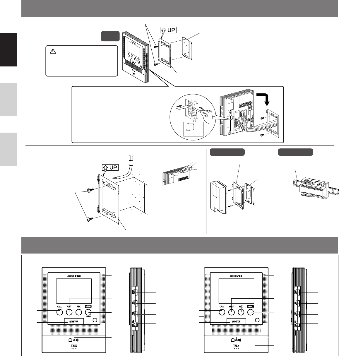
1. Press the RELEASE button (to insert or
remove the wire).
2. Insert the cable into the terminal.
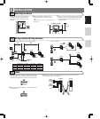
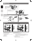
Back wiring
Mounting screws x 2
Mounting bracket
1-gang box
Peel off the protective film
from the display surfaces
of the JF-2MED and JF-
2HD.
Surface wiring
Wood mounting screws x 2
Din rail
Mounting bracket
Mounting bracket
1-gang box
*When a 1-gang box is not mounted,
the cable can be surface-run to the top
or bottom of the unit. Cut the cable
inlet to allow passage of the wiring
into the unit.
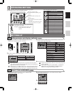
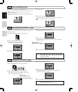
[1] Microphone
[2] Color LCD video monitor (3-1/2" color)
[3] CALL button, door call-in LED (red)
[4] PLAY button, play LED (red)
[5] REC button, record LED (red)
[6] MENU/MEMO button, memo LED (red) (JF-2MED)
MENU button (JF-2HD)
[7] POWER switch
[8] MONITOR button
[9] Speaker
[10] Transmit LED (red)
[11] TALK button
[12] Screen brightness control
[13] Receive volume control (high to off)
[14] Chime tone, alert sound volume (high to off)
NOTES: 1. Even when the volume is turned "Off", sometimes it may be possible to faintly
hear the entrance chime tone depending on the surrounding area.
2. The volume of chime tone and the notification sound will not change while they
are operating even if the volume control is adjusted. The adjusted volume will
apply from the next call-in or notification. (JF-2MED only)
[15] Call-in setting switch
"1": Call-in from door station 1 only.
"2": Call-in from door station 2 only.
"1&2": Call-in from both door station 1 and door station 2.
MOUNTING
4
NAMES
5
∗Cut open the cable inlet hole to
run wires to the back of the unit.
83,5 mm
(3-5/16")
83,5 mm
(3-5/16")
PS-1810DIN
JF-2MED
JF-2HD
PS-1820
83,5 mm
(3-5/16")
1
2
9mm
(3/8")
[1]
[2]
[3]
[5]
[4]
[7]
[6]
[10]
[11]
[8]
[9]
[12]
[13]
[14]
[15]
JF-2MED
[1]
[2]
[3]
[5]
[4]
[7]
[6]
[10]
[11]
[8]
[9]
[12]
[13]
[14]
[15]
JF-2HD


