- 4 -
EnglishFrançaisNederlands
JF-2MED
OP
EL-9S
OP
IER-2
1
E
L1
C1
L2
C2
L1
L2
RY-3DL JF-2MED
+
–
+
–
DC 18V
EL-9S
b1
b2
b3
D1
D2
E
EL-9S
PS18
OG(b1)
YE(b2)
GR(E)
L
BR(L)
RD(L)
PT
A1 A2
JF-DVF JF-DJF-DV
JF-DA
J
F
-
D
V
A
I
P
H
O
N
E
A
I
P
H
O
N
E
J
F
-
D
V
F
A
IP
H
O
N
E
J
F
-D
A
DOOR 2
A1 A2
JF-DVFJF-DV
JF-DA
J
F
-
D
V
A
I
P
H
O
N
E
A
I
P
H
O
N
E
J
F
-
D
V
F
A
IP
H
O
N
E
J
F
-D
A
DOOR 1
PS-1820
100V - 240V -
50/60 Hz
230V AC
N
L
18V DC
2 A
PS-1810DIN
18V DC 1 A
IN 230V~ 50/60Hz
NL
1A
-
+
-
+
#2 #1
#2
#1
E
KS
FS
PK
E
b2
V -
b1
V +
(BR)
(RD)
[1]
[2]
[7]
[3]
[4]
[6]
(OG)
(YE)
(GR)
(YE)
(BR)
(RD)
(OG)
(BL)
(PR)
(GY)
(WH)
SW
SW
L
L
[5]
PT
2
NP
[1]
DC 18 V
-
+
2
P
2
NP
2
NP
2
NP
PT
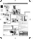
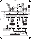
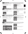
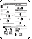
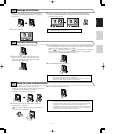
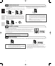
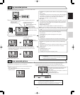
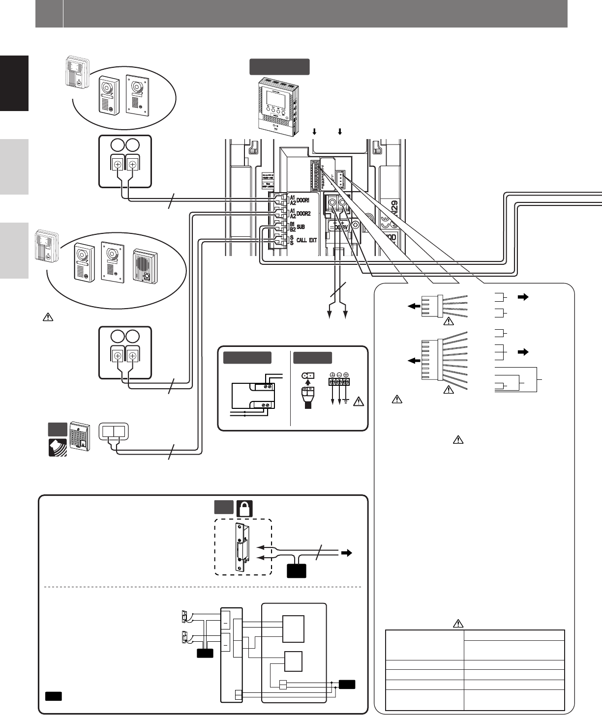
Insert wires securely into each terminal as shown.
Master monitor station
Video door station
Optional call extension speaker IER-2
Power supply +, - (DC 18 V)
(Audio only)
Setting is required. (Refer to section 7-7)
Control external devices connected with release connector and
option connector.
[1] Door release output
Setting is required. (Refer to section 7-8)
(AC/DC 24 V, 0.5 A N/O dry closure contact)
Connect the brown and red wires from the release connector to the
door release (or to the RY-3DL as shown in the wiring diagram).
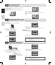
[2] Options output
(AC/DC 24 V, 1.6 A N/O dry closure contact)
[3] Video signal output
(NTSC, 1 Vp-p/75 Ω) Wiring distance: 3 m
NOTES: When video signal is output to the external
equipment, it may be possible to hear the buzz noise
from master station. Consult AIPHONE distributor.
[4] Door release-linked entrance output
[5] Press-to-talk setting input
If the blue and white wires are shorted, press-to-talk will not
be operable.
[6] Foot switch input
Connect a commercially-available foot switch to the purple
and white wires (N/O dry closure contact).
[7] External sensor input
Setting is required. (Refer to section 7-9)
Release connector
Option connector
Door release
or
RY-3DL
RY-3DL
Input method
N/O dry closure contact
External sensor input
(start signal only detection method)
Detection confirmation time 100 mS or more
Contact resistance
During dry closure: Less than 700 Ω
Terminal short current Less than 10 mA
Vo ltage between terminals
Less than DC 20 V
(when open between terminals)
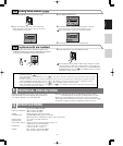
To prevent shorts, be sure to cut unused lead wires
at the bottom and insulate the ends.
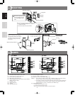
Door release EL-9S (AC 12 V, 0.35 A) or
equivalent, requires a separate AC transformer.
Run separate cables for audio/video and door
release.
Door release contact: AC/DC 24 V, 0.5 A
(N/O dry closure contact L, L).
Door release
Optional selective door release
adaptor RY-3DL
Use RY-3DL when connecting
door release to 2 locations.
Option connector
Release connector
WIRING
3
AC Transformer


