


F-26748-6 © Copyright 2010 Schneider Electric All Rights Reserved. 7
INSTALLATION
Inspection Inspect the package for damage. If damaged, notify the appropriate carrier immediately.
If undamaged, open the package and inspect the device for obvious damage. Return
damaged products.
Requirements • Job wiring diagrams
• Tools (not provided)
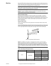
– Socket wrench 1/2 inch, used for universal mounting clamp nuts
– Open-end wrench 10 mm, used for installing AM-676 universal shaft extension
– Slotted screwdriver, used for installing anti-rotation brackets
– Allen wrench 3/16", used for manual override
• Appropriate accessories
– Water tight 1/2 inch conduit seals TAC part number TF-711-02 or T&B #5332
(straight, TAC part number TF-713-02 or T&B #5352 (90°), or equivalent.
– Water tight 1/2 inch flexible conduit (e.,g. Anaconda: Sealtight) or 20 mm flexible
water tight conduit when using AM-756 metric conduit adapter with appropriate
metric water tight seals.
– Water tight 1/2" flexible conduit (Anaconda: Sealtight) or 20 mm flexible water tight
conduit when using AM-756 metric conduit adaptor
– Two #8 1/2" (13 mm) sheet metal screws for mounting (optional)
• Training: Installer must be a qualified, experienced technician
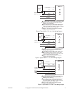
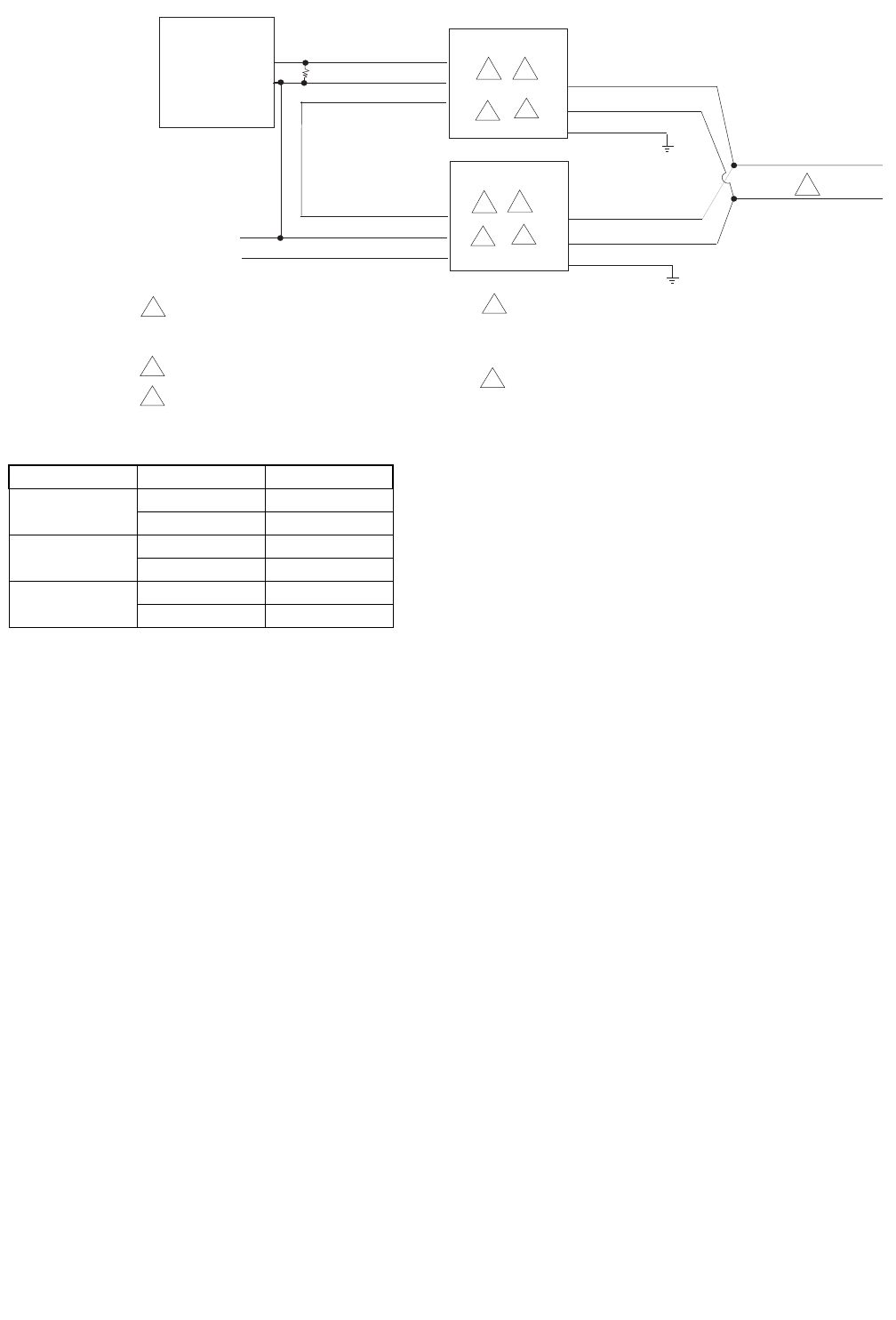
4 to 20 mA DC
Controller
(+) 4 to 20 mA DC
(-) Common DC
Power
GRD
GRD
1
1
2
MS40-717X
MS40-717X
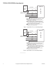
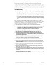
1 Unused conduit port must remain plugged with a
water tight pipe plug as shipped from factory to
maintain NEMA Type 4 or IP56 rating.
2 See table for power wire designations.
3 Both actuators must be set to operate in the same
direction.
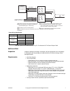
Yellow/Black
AI
Gray
Blue
AO
Yellow/Black
AI
Gray
Blue
AO
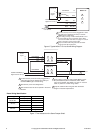
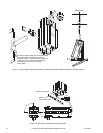
Position Feedback (-)
Signal 2 to 10 Vdc (+)
COM
COM
3
3
4
4
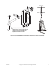
4 Color coding of wiring on older models (MX40-717x-0-
0-0) manufactured prior to December, 2007, differs
from current models. See Table 4 on page 14. Consult
label on product to confirm wiring codes.
5 Keep AI, COM and AO wiring less than 30 meters
length to meed CE requirements.
5
5
Green/Yellow
Green/Yellow
500 Ohm
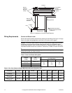
Figure-8 Typical 4 to 20 mAdc Control Wiring For Two Actuators On The Same Damper Shaft.
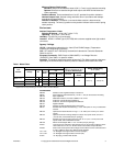
Power Wiring Identification.
Voltage Designation Wire Color
24 Vac or
22-30 Vdc
24H (DC+) Red
24G (DC-) Black
120 Vac
L1 Black
L2 White
240 Vac
L1 Brown
L2 Light Blue