


14 © Copyright 2010 Schneider Electric All Rights Reserved. F-26748-6
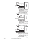
Wiring Requirements Control and Power Leads
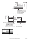
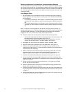
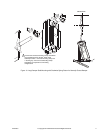
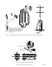
Remove blue plastic thread protectors before installing conduit fittings. See Figure-1 through
Figure 8 for typical wiring applications and Table-3 for maximum wire lengths.
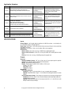
Caution: The 24 Vac model contains a half-wave rectifier power supply and must not be
powered by transformers used to power other devices utilizing non-isolated full-wave
rectifier power supplies. Refer to EN-206 Guidelines for Powering Multiple Full-Wave and
Half-Wave Rectifier Devices from a Common Transformer, F-26363, for further information.
Note: Class 2 control and power lead wiring must be routed separately from line voltage
wiring and any other non-class 2 circuits.
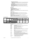
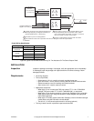
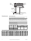
Table-3 Control and Power Wiring Data.
Table-4 Wire Color Codes for Models Manufactured before December, 2007.
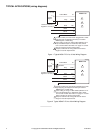
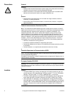
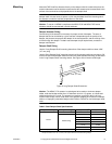
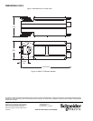
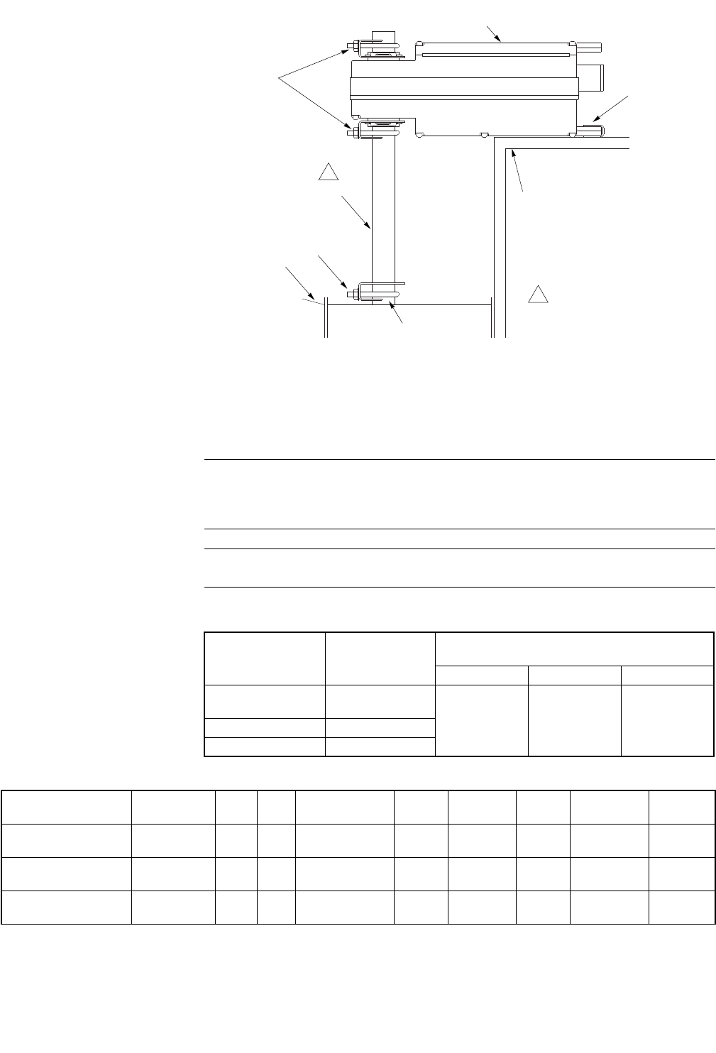
Figure-13 Installation of Universal Shaft Extension.
Actuator
Anti-rotation
Bracket
(included with
actuator)
AM-753
Universal
Mounting
Clamps
Duct
V-clamp
Mounting Surface
Damper Shaft
AM-676
Universal Shaft
Extension
1
1 The AM-676 extends the
damper shaft approximately
9" (229 mm).
Actuator
Voltage
Part
Number
Maximum Wire Run in ft. (m)
(5% Voltage Drop)
14 AWG 16 AWG 18 AWG
24 Vac and
22-30 Vdc
MS40-7173
981
(299)
617
(188)
388
(118)120 Vac MS40-7170
240 Vac MS40-7171
Part Number
Power
Voltage
L1 L2 Ground 24 H 24 G
Analog
Input
500 Ohms Common
MS40-7173-0-0-0
Old Design
24 Vac N/A N/A Green/Yellow Black Black/Blue White Red Black
MS40-7170-0-0-0
Old Design
120 Vac Black White Green/Yellow N/A N/A White Red Black
MS40-7171-0-0-0
Old Design
240 Vac Brown
Light
Blue
Green/Yellow N/A N/A White Red Black
N/A: Not Applicable