


10 © Copyright 2010 Schneider Electric All Rights Reserved. F-26748-6
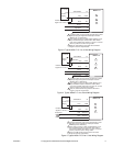
Mounting the Actuator for Clockwise or Counterclockwise Dampers
The zero (0) position on the position indicator is the normal or spring return position. When
the actuator is mounted with the “R” side facing the installer and the control signal increases
the actuator will rotate in the counterclockwise direction. When the actuator is mounted with
the “L” side facing the installer and the control signal increases the actuator will rotate in the
clockwise direction.
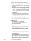
Long Damper Shafts
1. Move the damper to its normal position. Verify the controller action is set to match the
damper application (normally closed or normally open). See TYPICAL APPLICATIONS
(wiring diagrams).
– For normally closed damper, when damper is closed the actuator position indicator
should be at 0°. When damper is open the actuator position indicator should be at
90°.
– For normally opened damper, when damper is open the actuator position indicator
should be at 0°. When damper is closed the actuator position indicator should be at
90°.
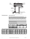
Note: The actuator comes equipped with two AM-754 universal mounting clamps. For
damper shafts larger than 1/2" (13 mm) in diameter, the AM-753 universal mounting clamps
are required (order separately). The AM-753 clamps accommodate round shaft sizes
ranging from 3/4" to 1" (19 to 25 mm) or 5/8" (16 mm) square shafts.
2. Slide the actuator over the shaft and into its desired final mounting position.
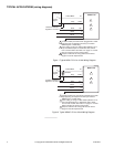
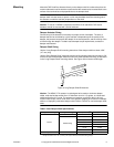
– If the damper shaft rotates clockwise to the closed position, mount the actuator with
the side marked “R” facing the installer. See Figure-10.
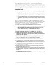
– If the damper shaft rotates counterclockwise to the closed position, mount the
actuator with the side marked “L” facing the installer. See Figure-11.
3. Hand tighten the nuts on both of the actuator’s universal mounting clamps.
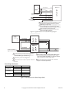
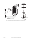
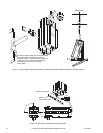
4. Align the actuator at 90° (perpendicular) to the damper shaft. See Figure-12.
5. Slide the anti-rotation bracket pin into the mounting slot on the actuator and drill
mounting holes. See Figure-12. For narrow spaces the AM-752 anti-rotation bracket is
recommended (order separately).
6. Attach one side of the anti-rotation bracket to the mounting surface with one of the
screws provided. Leave the screw loose so that the bracket can be rotated. See
Figure-10 for clockwise or Figure-11 for counterclockwise spring return.
7. Pivot the anti-rotation bracket away from the actuator. See Figure-10 or Figure-11.
8. Loosen the universal mounting clamps, making sure not to move the damper shaft.
Rotate the actuator approximately 5° in the direction which would open the damper. See
Figure-10 or Figure-11.
9. Tighten all of the universal mounting clamp nuts with a 1/2" socket wrench. Apply
4 to 6 ft -lbs (5 to 8 N-m) of torque.
10. Manually rotate the actuator toward the full-closed position to apply pressure to the
damper seals. See Figure-10 or Figure-11.
11. Pivot the anti-rotation bracket into place and secure the other side of the bracket onto
the mounting surface using the other screw provided with the actuator. See Figure-10
or Figure-11.
12. Verify that the damper is in its full-closed position and actuator at 90° (perpendicular) to
the damper shaft. See Figure-10 or Figure-11.