


F-26748-6 © Copyright 2010 Schneider Electric All Rights Reserved. 5
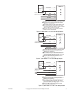
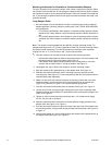
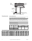
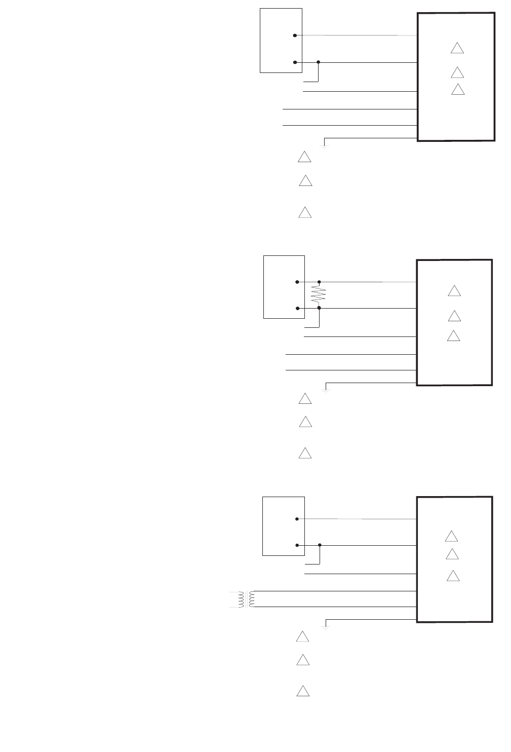
MS40-7171
Brown
Light Blue
L1
L2
240 Vac
GRDGreen/Yellow
Yellow/Black
Gray
AI
COM
2 to 10 Vdc
+
-
Control
Signal
1
Position Feedback (-)
Signal 2 to 10 Vdc (+)
Blue AO
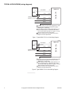
1 Unused conduit port must remain plugged with a water
tight pipe plug as shipped from factory to maintain
NEMA Type 4 or IP56 rating.
2 Color coding of wiring on older models (MX40-717x-0-
0-0) manufactured prior to December, 2007, differs
from current models. See Table 4 on page 14. Consult
label on product to confirm wiring codes.
3 Keep AI, COM and AO wiring less than 30 meters
length to meet CE requirements.
2
3
Figure-3 Typical MS40-7171 2 to 10 Vdc Wiring Diagram.
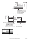
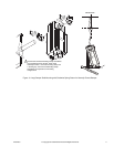
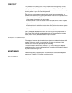
MS40-7171
Brown
Light Blue
L1
L2
240 Vac
GRDGreen/Yellow
Yellow/Black
Gray
AI
COM
4 to 20 mA
+
-
500 Ohm
1
Position Feedback (-)
Signal 2 to 10 Vdc (+)
Blue AO
Control
Signal
1 Unused conduit port must remain plugged with a water
tight pipe plug as shipped from factory to maintain
NEMA Type 4 or IP56 rating.
2 Color coding of wiring on older models (MX40-717x-0-
0-0) manufactured prior to December, 2007, differs
from current models. See Table 4 on page 14. Consult
label on product to confirm wiring codes.
3 Keep AI, COM and AO wiring less than 30 meters
length to meet CE requirements.
2
3
Figure-4 Typical MS40-7171 4 to 20 mA Wiring Diagram.
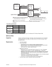
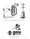
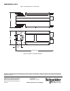
MS40-7173
Red
Black
24H (DC+)
24G (DC-)
24 Vac or 22-30 Vdc
GRDGreen/Yellow
Yellow/Black
Gray
AI
COM
+
-
2 to 10 Vdc
1
Transformer
Control
Signal
Position Feedback (-)
Signal 2 to 10 Vdc (+)
Blue AO
1 Unused conduit port must remain plugged with a water
tight pipe plug as shipped from factory to maintain
NEMA Type 4 or IP56 rating.
2 Color coding of wiring on older models (MX40-717x-0-
0-0) manufactured prior to December, 2007, differs
from current models. See Table 4 on page 14. Consult
label on product to confirm wiring codes.
3 Keep AI, COM and AO wiring less than 30 meters
length to meet CE requirements.
2
3
Figure-5 Typical MS40-7173 2 to 10 Vdc Wiring Diagram.