


F-26748-6 © Copyright 2010 Schneider Electric All Rights Reserved. 13
Short Damper Shafts
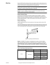
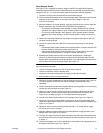
See Figure-13 for installation of actuator using the AM-676 Universal Shaft Extension.
Installation requires AM-676 Universal Shaft Extension and AM-753 Universal Mounting
Clamps for 3/4" to 1" (19 to 25 mm) shafts, these items must be ordered separately.
1. Loosen the V-clamp nuts on the AM-676 universal shaft extension.
2. Fit the universal shaft extension fully onto the damper shaft. Tighten the universal shaft
extension V-clamp nuts with a 10 mm open-end wrench. Apply 4 to 6 ft. lbs
(5 to 8 N-m) of torque.
3. Move the damper to its normal position. Verify the controller action is set to match the
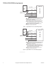
damper application. See TYPICAL APPLICATIONS (wiring diagrams).
– For normally closed damper: when damper is closed, actuator position indicator
should be at 0°. When damper is open, actuator position indicator should be at 90°.
– For normally opened damper: when damper is open, actuator position indicator
should be at 0°. When damper is closed, actuator position indicator should be at
90°.
4. Remove the mounting clamps from the actuator and replace them with the AM-753
universal mounting clamps.
5. Loosen the nuts on both of the AM-753 universal mounting clamps on the damper
actuator.
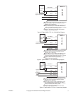
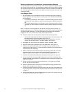
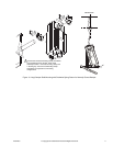
– If the damper shaft rotates clockwise to the closed position, mount the actuator with
the side marked “R” facing the installer. See Figure-10.
– If the damper shaft rotates counterclockwise to the closed position, mount the
actuator with the side marked “L” facing the installer. See Figure-11.
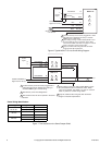
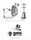
6. Assemble the damper actuator onto the universal shaft extension, allowing the
extension to slide through the actuator’s universal mounting clamps. Make sure the
actuator is 90° (perpendicular) to the damper shaft. Then, hand tighten the nuts on both
of the actuator’s universal mounting clamps. See Figure-12
Note: If the universal shaft extension protrudes excessively above the damper actuator's
top universal mounting clamp:
• remove the damper actuator from the universal shaft extension,
• remove the extension from the damper shaft,
• shorten the universal shaft extension by cutting it to the desired length,
• then proceed to follow mounting instructions.
7. Slide the anti-rotation bracket pin into the mounting slot on the actuator. See Figure-12.
For narrow spaces, the AM-752 anti-rotation bracket is recommended (order
separately).
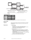
8. Position the actuator and bracket in the desired final mounting position on the mounting
surface and drill mounting holes. See Figure-13.
9. Attach one side of the anti-rotation bracket to the mounting surface with one of the
screws provided. Leave the screw loose so that the bracket can be rotated. See
Figure-10 for clockwise or Figure-11 for counterclockwise spring return.
10. Pivot the anti-rotation bracket away from the actuator. See Figure-10 or Figure-11.
11. Loosen the universal mounting clamps, making sure not to move the damper shaft.
Rotate the actuator approximately 5° in the direction which would open the damper. See
Figure-10 or Figure-11.
12. Tighten all of the universal mounting clamp nuts with a 1/2" socket wrench. Apply
4 to 6 ft-lbs (5 to 8 N-m) of torque.
13. Manually rotate the actuator toward the full-closed position to apply pressure to the
damper seals. See Figure-10 or Figure-11.
14. Pivot the anti-rotation bracket into place and secure the other side of the bracket onto
the mounting surface using the other screw provided with the actuator. See Figure-10
or Figure-11.
15. Verify that the damper is in its full-closed position and actuator at 90° (perpendicular) to
the damper shaft. See Figure-10 or Figure-11.