


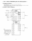
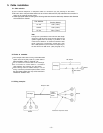
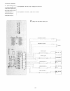

Central control unit CC-20:
This unit is comprised of a CPU that processes the exchange procedures, a speech link consisting of a
voice switch circuit and a signal tone generating circuit, and a power circuit.
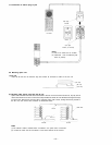
Line modem unit LM-20:
This unit is comprised of a circuit for sending out signals from the station to the speech path, a circuit to
transmit signals from the speech link to the station, a receiver and a scanning circuit for dial data, and a
terminal block. Wires from the station are connected directly to the terminal block on the LM unit. A
maximum of 4 stations can be connected per LM unit, and up to 4 LM units can be mounted in the EX-200
and FC-210.
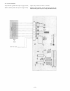
BGM unit BI-20:
This unit is comprised of a circuit to send out signals from BGM equipment, and alarm or time signals to
the LM unit, a circuit that transmits control signals from the alarm or timer to the CPU, and a terminal
block. The Bl unit is mounted in the exchange from the bay solely intended for this unit.
Remote control unit RC-20:
This unit is formed from relays for door remote control, power remote control and PTT control, a circuit to
activate these relays, and a terminal block. It is possible to use any bay for "option" unit to mount the
RC-20 in the exchange.
Pager control unit PC20:
This unit has the control output to remotely operate the TR-321 or TR-322 pager controller as well as the
serial data output that complies with ESPA standards. The PC-20 may be mounted in the exchange from
any bay for "option" unit.
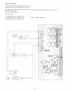
Speech message unit SM-20:
This unit includes a circuit to convert audio signals into digital signals, a memory storing the converted
signals, and a circuit that converts digital signals into audio signals. A single SM unit has a memory
covering 4 stations, and a control circuit. A maximum of 5 SM units can be mounted in the EX-200
exchange (in this event, no room is left for mounting the RC unit, PC unit and Tl unit in the exchange), and
up to 6 in the FC-210 cabinet. However, an entire system can only accept up to 8 of the SM-20 unit.
Tie-line unit TI-20:
This unit is comprised of DTMF transmitting and receiving circuits for exchanging dial data with the other
exchange, and a circuit for transmitting voice signals.
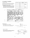
Power transformer unit PU-200:
This unit supplies power to the EX-200 and the FC-210. Power output is 20V AC, 2.5 amperes for both
exchanges.
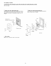
Extension cabinet FC-210:
This unit is employed when a system has more than 16 stations or a number of "option" units are used. A
maximum of 4 LM-20's and 6 "option" units can be mounted in the FC-210. Note that the YR-820 and
YR-821 cables are necessary for adding the LM-20 and the "option" unit, respectively.
– 3 –