


4 947101
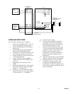
__ (c) On one column of the block, completely
punch down a 25 pair cable. The other end
of the cable should have a female amphenol
connector.
__ (d) Plug the amphenol connector into the
V-1101A.
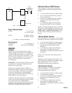
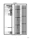
__ (e) Mark the punch down block as shown in
Figure 2.
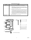
Power Connections
__ 1. Unplug power supply.
__ 2. Connect –24 Vdc "B" battery (may be
referred to as "–" or "signal battery") from
power supply to BB (S/V) of the V-1101A.
__ 3. Connect –24 Vdc Ground ("B" ground, "+",
or "signal" ground) from the power supply to
BG (V/S).
__ 4. Connect –24 Vdc "A" battery (may be
referred to as "–" or "talk battery") from the
power supply to AB (BR/V) of the
V-1101A.
__ 5. Connect –24 Vdc Ground ("A" ground, "+",
or "talk ground") from the power supply to
AG (V/BR).
__ 6. Connect GROUND from the power supply
to a good Earth or Water Pipe ground.
7. Power Test:
__ (a) Plug in power supply.
__ (b) Using a screwdriver, momentarily short
between the BFT (W/S) and BFR (S/W)
leads of the V-1101A and listen for a relay
to operate in the unit.
__ (c) If no relay is heard:
__ (1) Unplug power supply.
__ (2) Verify the V/BR and V/S pairs are
properly connected at the
punch-down block and in the
amphenol.
__ (3) Return to step 2, and verify all
connections.
__ (d) If a relay is heard, proceed to step 8.
__ 8. Unplug power supply.
Connecting Arrangements
NOTE: Place a check by the arrangement being used
and proceed to the Figure indicated for step-by-step
installation instructions.
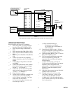
__ 1. Electronic key system line key access:
Proceed to Figure 3.
__ 2. PABX loop trunk port access:
Proceed to Figure 3.
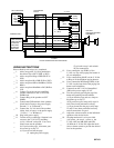
__ 3. 1A2 key system line button access:
Proceed to Figure 4.
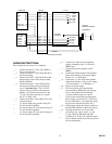
__ 4. 1A2 key system intercom access:
Proceed to Figure 5.
__ 5. Electronic key or PABX page port access:
Proceed to Figure 6.