


Sampling Rate Register
4-13
Software
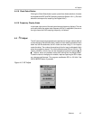
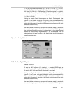
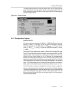
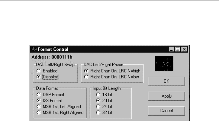
The Apply button sends the current bit values shown on the Analog Control
panel to the Audio (Format) register section of the register panel. The OK
button performs the same function as the Apply button and simultaneously
closes the register panel.
Figure 4–8. Format Control
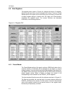
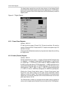
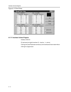
4.6.11 Sampling Rate Register
Address: 0001000
D7 sets the clock output divider (0 = MCLK, 1 = MCLK/2), D6 sets clock input
divider (0 = MCLK, 1 = MCLK/2). D5–D2 set the SR3–SR0 bits. D1 sets the
base oversampling rate (In USB mode, 0 = 250 f
S
and
1 = 272 f
S
; in normal
mode, 0 = 256 f
S
and
1 = 384 f
S
). D0 sets the USB/normal mode (0 = normal,
1 = USB).
Clicking the Clock Select button opens a Normal Clock Setup panel (see
Figure 4–9) that allows the selection of master clock speed and ADC and DAC
sampling rates. There are also two check boxes for setting the clock input
divider and clock output divider on or off. Because the correspondence
between clock settings and register bit values is not intuitively obvious, it may
be easier to input the desired clock frequency and sampling rates in the Normal
Clock Setup panel and observe the bit settings that appear in the registers
panel. The Clock Select button in the sampling rate register box is functionally
identical to the Clock Select button on the main panel (see Section 4.4.18).
The Cancel button undoes any changes that have been made in register bit
values, so the register panel matches the current state of the EVM registers.
The Apply button sends the current bit values shown on the Analog Control
panel to the Sampling Rate register section of the register panel. The OK
button performs the same function as the Apply button and simultaneously
closes the register panel.