


Power Down Register
4-12
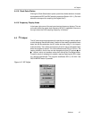
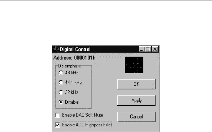
The Apply button sends the current bit values shown on the Analog Control
panel to the Audio (Digital) register section of the register panel. The OK button
performs the same function as the Apply button and simultaneously closes the
register panel.
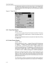
Figure 4–7. Digital Control
4.6.9 Power Down Register
Address: 0000110
D7 sets the device power. D6 sets CLK. D5 sets the oscillator. D4 sets the
outputs. D3 sets the DAC. D2 sets the ADC. D1 sets the microphone input. D0
sets the line input.
Clicking the Send Data button sends only the power down data without clicking
the Apply button.
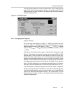
4.6.10 Audio (Format) Register
Address: 0000111
D6 sets master/slave (0 = slave, 1 = master). D5 sets the DAC left/right swap
(0 = disabled, 1 = enabled). D4 sets the DAC left/right phase (0 = right channel
on, LRCIN high, 1 = LRCIN low). In DSP mode (0 = MSB is available on the
first BCLK rising edge after an LRCIN rising edge, 1 = MSB is available on the
second BCLK rising edge after an LRCIN rising edge). D3–D2 set the input
word length (00 = 16b, 01 = 20b, 10 = 24b, 11 = 32b). D1–D0 set the data format
(11 = DSP; 10 = I
2
S; 01 = MSB first, left aligned; 00 = MSB first, right aligned).
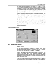
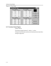
Clicking the Format Control button opens a Format Control panel (see
Figure 4–8) that allows setting all the audio format parameters without
reference to their bit values. The Format Control button in the audio format
register box is functionally identical to the Format Control button on the main
panel (see Section 4.4.16).
The Cancel button undoes any changes that have been made in register bit
values, so the register panel matches the current state of the EVM registers.