


Digital I/O
3-7
Theory of Operation
3.5 Digital I/O
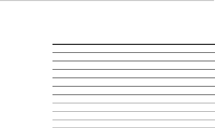
A protected header, J7, is available for interfacing with external digital I/O. Two
power sources, 5 V and 3.3 V, are available on J7 for powering external
boards. The 5-V power is tapped directly off PJ1. The 3.3-V power can supply
up to 100 mA.
Signal J7
5v_DIO (5.0 VDC) 1, 2
VCC_DIO (3.0 VDC) 5, 6
DIN 9
DOUT 11
BCLK 13
LRCIN 15
LRCOUT 17
MCLK 19
DIGITAL GROUND 3, 4, 7, 8, 10, 12, 14, 16, 18, 20
3.6 TLV320AIC23 EVM2 Features
3.6.1 Master Clock
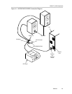
The master clock can be either external or internal. For internal mode, a crystal
socket is available. For external mode, the master clock is applied to SMA jack
J8. The master clock input is 5-V tolerant. The master clock output is available
at SMA jack J6. The master clock is derived from the CLKOUT pin (U1 pin 2).
This signal has a 5-V swing.
3.6.2 Digital Loopback
Digital loopback can be enabled using the GUI. This loops DOUT to DIN via
a MUX.
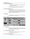
3.6.3 Software Interface Connection
A PC provides control of the TLV320AIC23 EVM2 via a software GUI called
Rhino. A parallel port interface board, DAREF106, connects to the PC parallel
port. A cable with miniDIN 8-pin connectors, included in the TLV320AIC23
EVM2 kit, connects the parallel port interface board to the EVM.