


10
5.
Press the tabs firmly into position.
6.
7.
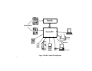
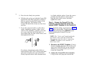
With the tabs at the top, hold the ConnecT/R
against the wall where you plan to mount it
and use a pencil to mark the location of the
holes in the tabs. The bottom of the
ConnecT/R should be at least two feet from
the floor.
If you have plywood walls or walls with a
sturdy supporting structure (either wood
studs or cross members), partially screw the
two screws into the wall at the marks, re-
move them, hang the tabs on the screws, and
then tighten the screws.
For plaster, plasterboard, cinder block or
brick surfaces, drill a 3/16" hole at each mark
and insert an anchor into each of the holes.
Gently tap each anchor with a hammer until
it is flush with the surface. Screw the screws
partially into the anchors, remove them,
hang the tabs on the screws, and then
tighten the screws.
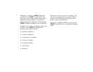
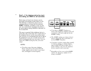
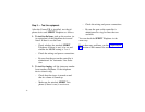
Step 4 —
Connect the ConnecT/R to the
controller, and the telephone device and
optional SPIRIT Telephone to the ConnecT/R.
Please check the cabling requirements in Appen-
dix A before proceeding. Consult with the
person who customized your SPIRIT System
before attaching the ConnecT/R to the
controller.
NOTE: The "4-wire cord" mentioned in the
steps below comes with the ConnecT/R.
Any cord you may have that is connecting
a
SPIRIT
Telephone to the controller is
also 4-wire cord.
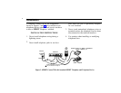
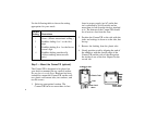
1.
Disconnect the SPIRIT Telephone.
If one is
already installed, disconnect it from the wall
jack or the STATION jack on the controller,
whichever is closest to where you want to
locate the ConnecT/R.
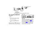
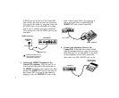
2.
Connect the ConnecT/R to the Controller.
Using 4-wire cord, plug one end into the