


15
Appendix A
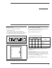
Internal Access
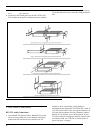
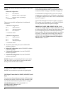
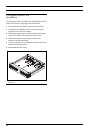
1. Remove six screws from the back cover.
2. Remove the top cover.
This provides access to all internal adjustments.
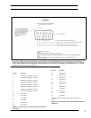
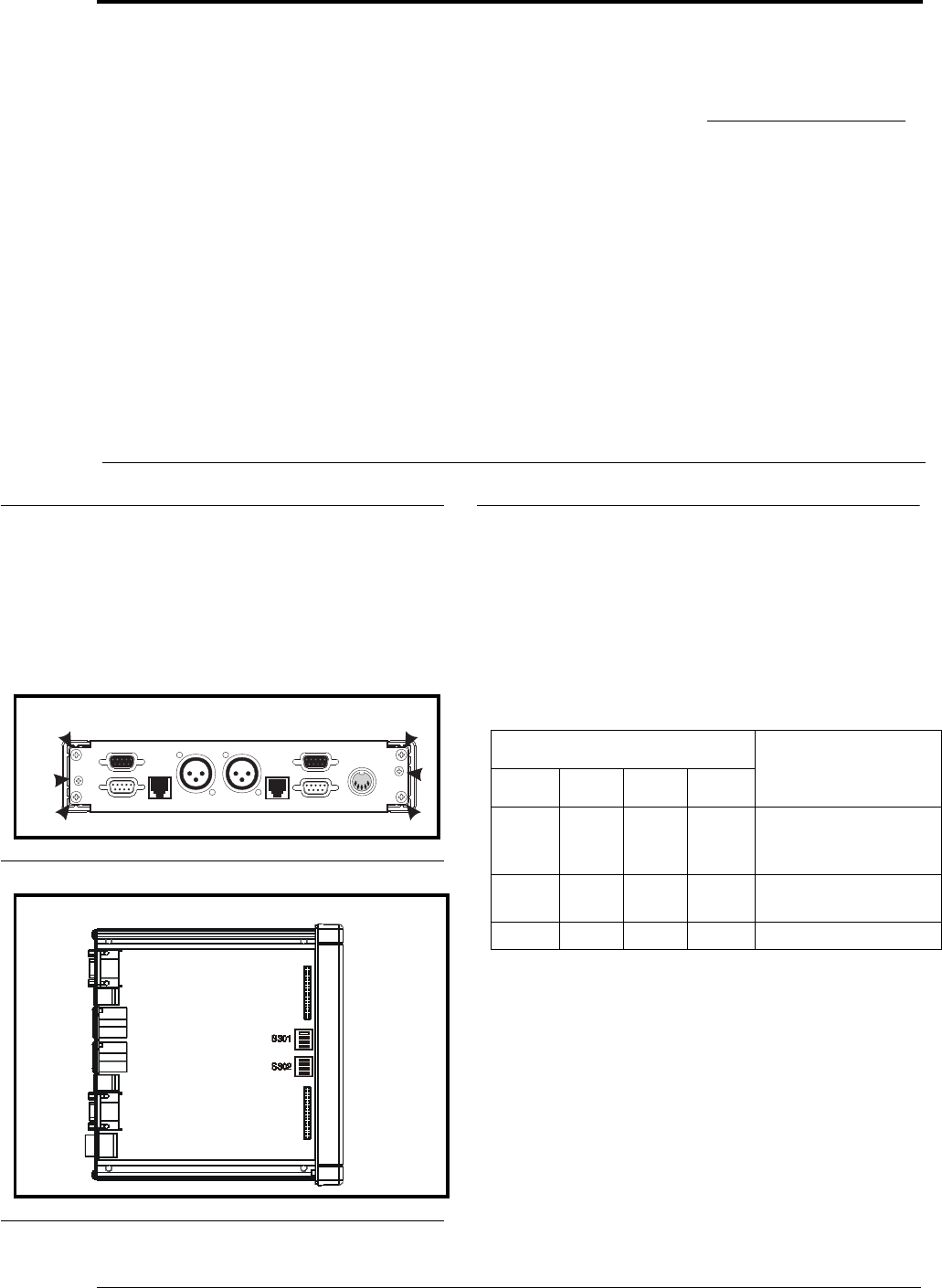
3. For option card installation, slide the circuit board out
toward the back to remove it from the bottom cover.
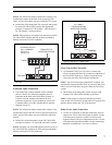
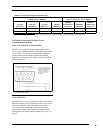
Mode Dip Switch Settings
S301 controls the operating mode for System B and S302
controls the operating mode for System A.
Settings are summarized as follows:
Full-Duplex Definition: Both sides of the line can talk
simultaneously.
Half-Duplex Definition: Only one side of the line can talk
at a time and the other side must wait until the first side is
done talking before responding. 4-wire systems have priority
over 2-wire system in Half-duplex mode.
Tone Test Mode: Disables internal suppression of tones.
FIGURE 1. Location of screws for disassembly.
FIGURE 2. Locations of internal controls
AUX
J4B
J3B
J2B
J1B
J1A
J2A
J3A
J4A
AUX
4 WIRE SYSTEM 4WIRE SYSTEM
2 WIRE SYSTEM
Telex Communications, Inc., Made in U.S.A.
RTN
+5V
RTN
+15V -15V
-15V 0.3A
+15V 1.6A
+5V 3A
J5 POWER
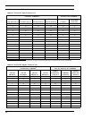
TABLE 1. Mode DIP Switch Settings
Switch Settings
Description
1234
Open Open Open Open Configuration 1,
Full-Duplex Mode
(Default)
Closed Open Open Open Configuration 2,
Half-Duplex Mode
Open Open Open Closed Tone Test Mode