


9
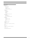
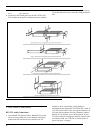
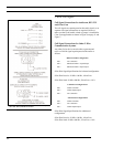
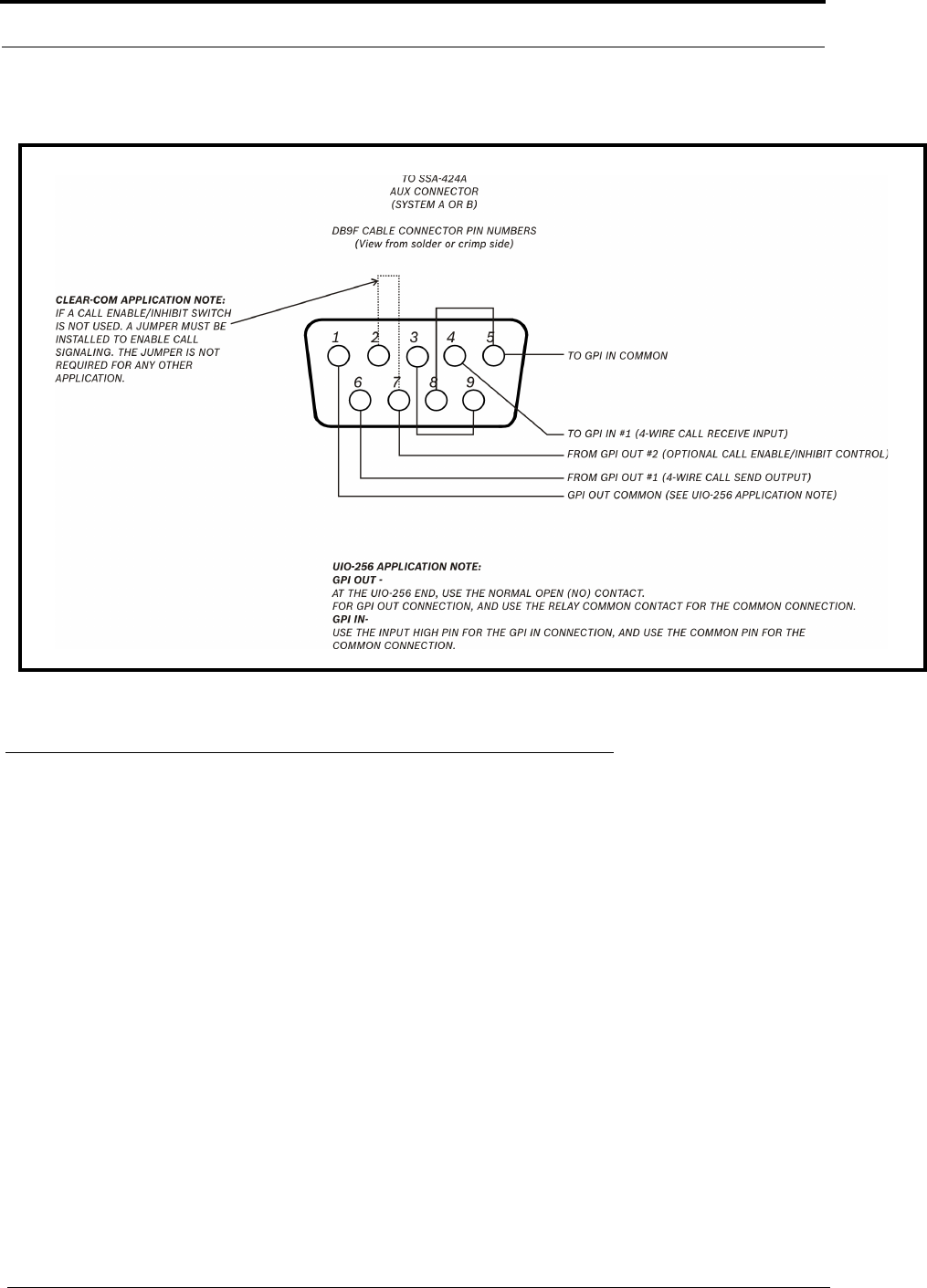
4-Wire Call Signal Connections
FIGURE 5. Call signal connections for ADAM, ADAM CS, and Zeus Intercom Systems. This example uses GPI outputs #1 and #2 and GPI Input
#1; however, you may use any other available GPI inputs and outputs. The Call Enable/Inhibit connection is optional. It gives you the ability to
disable call signalling using a GPI output. However, when connecting to a Clear-Com intercom system, if an enable/inhibit switch is not connected, a
jumper must be installed for any other application. You DO NOT have to use GPI outputs for call signalling or enable/inhibit, you can use simple
switches instead, as shown in Figure 6 on page 11.
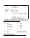
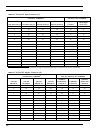
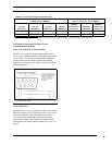
Pin No. Function
1 GPI Input #1 High (5-18 VDC)
2 GPI Input #2 High (5-18 VDC)
3 GPI Input #3 High (5-18 VDC)
4 GPI Input #4 High (5-18 VDC)
5 GPI Input #5 High (5-18 VDC)
6 GPI Input #6 High (5-18 VDC)
7 GPI Input #7 High (5-18 VDC)
8 GPI Input #8 High (5-18 VDC)
9 Common*
10 Common*
11 Common*
12 Common*
13 Common*
14 GPI Out #1
TABLE 1. GPI Connector Pin-out (ADAM, ADAM CS,
and Zeus)
15 GPI Out #2
16 GPI Out #3
17 GPI Out #4
18 GPI Out #5
19 GPI Out #6
20 GPI Out #7
21 GPI Out #8
22 Common*
23 Common*
24 Common*
25 Common*
*Use any available common pin with any GPI Input or
Output.
Pin No. Function
TABLE 1. GPI Connector Pin-out (ADAM, ADAM CS,
and Zeus)