


13
CHAPTER 3
Operation
General Instructions
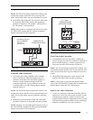
1. Attach the power pack to the SSA-424A and apply power
to all components. Confirm the power indicator is lit on
the SSA-424A front panel.
NOTE: The power indicator flashes when a call signal is
received from a 2-wire line, if the call signal option board is
attached. The SSA-424A level displays should help to
confirm which line is calling.
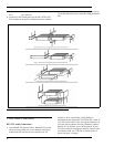
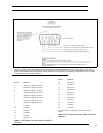
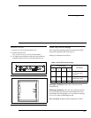
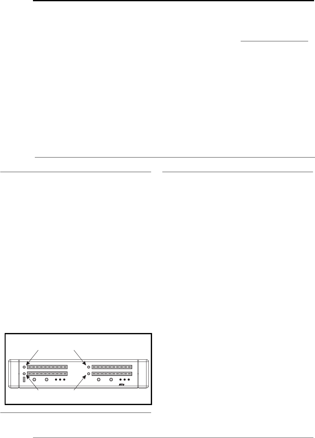
2. Use the level adjust trimmers (Figure 8) to fine tune the
listen levels.
NOTE: For 4-wire systems other than ADAM, ADAM CS,
and Zeus, you may have to change the setting of the 4W
LEVEL REF SEL control to establish the correct level. For
2-wire system other than Audiocom, TW, and Clear-Com,
you may have to adjust the level at the 2-wire system if you
cannot establish the correct level with the 2-wire listen level
trimmers.
Operating Notes for ADAM, ADAM CS
and Zeus Intercom Systems
1. In AZedit use port alpha setup to name each 4-wire
intercom port that is connected to the SSA-424A. Choose
names which help indicate which 2-wire line is being
interfaced.
2. Key assignment, party line assignment, etc. is the same
as for any other intercom port.
3. Optional call signal output using the GPI: you can assign
the GPI output to a talk or listen key, then activate that
key to generate a call signal.
Another way to generate a call signal is by assigning the
GPI output as a level 2 talk key assignment for any key
that is assigned to talk to the SSA-424A. However, this
will cause the call lights to flash on the 2-wire line during
the entire conversation.
Another solution is to assign a dedicated key as a UPL
resource key (which you could name CALL). Then for
each key that talks to an SSA-424A hybrid, create a UPL
statement that will activate the appropriate GPI whenever
the call key and the talk key are pressed. This lets you use
the same call key with more than one GPI. To use, simply
activate the call key and the appropriate talk key. Then,
when a verbal response is received, release the call key.
FIGURE 8. Location of level adjust trimmers
-15 -12 -9
-6 0
+3 +6 +9
+12
LEVEL
SET
SYSTEM B
-15 -12 -9
-6 -3
0
+3 +6 +9
+12
4W
2W
TO
TO
SSA-424A
4W LEVEL
REF SEL
12
BAL
2W CHAN SEL
LEVEL
SET
SYSTEM A
-3
4W
2W
TO
TO
POWER
4W LEVEL
REF SEL
12
BAL
2W CHAN SEL
1
2
BAL
OFF
OFF
TM
0dB
+4dB
+8dB
+12dB
-10dB
0dB
+4dB
+8dB
+12dB
-10dB
1
2
BAL
OFF
OFF
4-WIRE LISTEN LEVEL ADJUSTMENT
2-WIRE LISTEN LEVEL ADJUSTMENT