


11
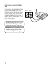
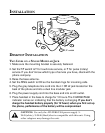
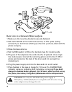
EACH LINE ON A SEPARATE MODULAR JACK
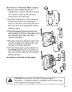
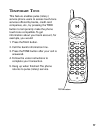
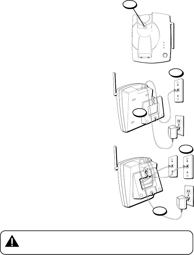
1. Remove the handset hook; turn it
upside down, and put it back in the slot.
You need to do this so the handset
doesn’t fall out of the base.
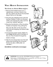
2. Reverse the direction of the mounting
bracket and replace it by putting the
tabs into the slots on the top of the unit
first, and then by snapping the bottom
tabs into place.
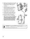
3. Plug the telephone line cord into the
jack marked L1 OR L2 on the back of the
unit and plug the other end into a
modular wall jack.
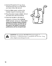
4. Plug the remaining telephone line cord
into the L2 jack on the back of the unit
and into a modular wall jack.
5. Connect the power supply adapter to
the POWER 9V DC jack on the back of
the unit, and then thread it through the
bottom of base.
(Installation continued on next page.)
2
3
5
4
PAG E
LINE 1
LINE 2
CHARGE
PAG E
1
CAUTION: Use only the ATLINKS USA power supply 5-
2445(white)/ 5-2446(black)that is compatible with this unit. Using
other adapters may damage the unit.