


SA7—6
5. Install C5, .01 uF. Notice that C5 lines up with the DC voltage supply points on the PC board. If you
have your red (+) and black (-) supply wires ready, they could be installed now while correct polarity is
on your mind.
6. Install R4, 1K ohms (brown-black-red). Note that this resistor is installed vertically, with the resistor
body closest to Q1.
7. Install C4, the one electrolytic capacitor. Make sure polarity is correct.
8. Install R5, 100 ohm (brown-black-brown).
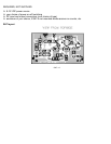
9. Install Q1 and Q2, 2SC2498 or 2SC2570A. Both transistors are identical. Press both into their
respective PC board holes, now made very obvious by the installation of the previous parts. Orient the
flat sides as shown on the PC board illustration. Press both in firmly with finger pressure so that a
minimum amount of wire leads are exposed above the PC board. Bend the inserted leads in opposing
directions just enough to hold each transistor in place. In soldering, do not be afraid to apply enough
heat to make good, solid connections.
10. Install L1, the small pre-wound coil.
11. Install C3, .01 uF.
12. Install R3, 470 ohms (yellow-violet-brown).